Automatic metal ball conveying mechanism

A ball and metal technology, applied in the field of metal ball automatic transmission mechanism, can solve the problems of multi-operation of the driving mechanism, troublesome, difficult to place and process the balls continuously and accurately, and achieve the effect of reasonable structure design.

Active Publication Date: 2020-04-14
桐乡市红旗塑料包装袋厂
View PDF5 Cites 2 Cited by
  • Summary
  • Abstract
  • Description
  • Claims
  • Application Information

AI Technical Summary

Problems solved by technology

[0002] Mechanical workpieces are single parts that make up machinery and machines that cannot be separated. It plays an important role in the automation industry. Mechanical workpieces include the connection of parts, supporting parts, lubricating lubrication systems and sealing parts. Components, parts of the transmission system that transmit motion and energy, there are many types of workpieces, and shaft sleeve workpieces are especially widely used in industrial production and mechanical equipment. The main function of shaft sleeve workpieces on mechanical equipment is axial positioning, The role of dustproof, sealing and torque transmission, during the production and processing of shaft sleeve workpieces, it is necessary to place multiple balls evenly on the outside of the shaft tube part of the shaft sleeve workpiece, so that the shaft sleeve workpiece can realize shaft rotation during specific use. In the process of placing the balls of the existing shaft sleeve workpieces, the balls are placed one by one manually, the work intensity of the workers is relatively high and the work efficiency is low, and the existing balls are usually placed by manipulators The balls are grasped and placed, but the manipulator is used for grasping and placing, the driving mechanism is more and the operation is troublesome, it is difficult to realize the continuous and accurate placement of the balls, and because the ball particles have a circular structure, the manipulator is in the process of grasping the balls. It is difficult to achieve stable and efficient grabbing and fixing, and it is very easy to cause the balls to fall off during the ball grabbing and transferring process, which affects the normal and orderly ball feeding process. In the process, it is difficult to realize the smooth and efficient transfer and loading of balls one by one, and the balls cannot be automatically guided to the desired position. The automation of ball feeding and transmission is low, which affects the ball placement efficiency and quality of shaft sleeve workpieces, and reduces The production and processing speed of shaft sleeve workpieces cannot meet the needs of processing and use

Method used


Image

  • Automatic metal ball conveying mechanism
  • Automatic metal ball conveying mechanism
  • Automatic metal ball conveying mechanism

Examples


Embodiment Construction

[0014] In order to further describe the present invention, the specific implementation of a metal ball automatic feeding mechanism will be further described below in conjunction with the accompanying drawings. The following examples are explanations of the present invention and the present invention is not limited to the following examples.

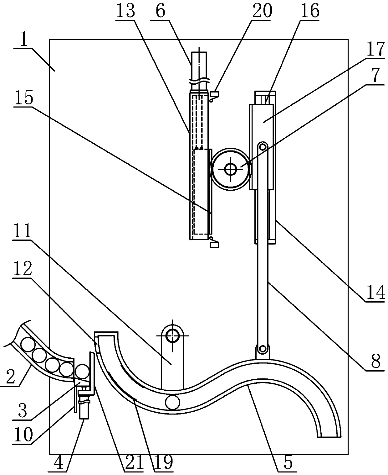
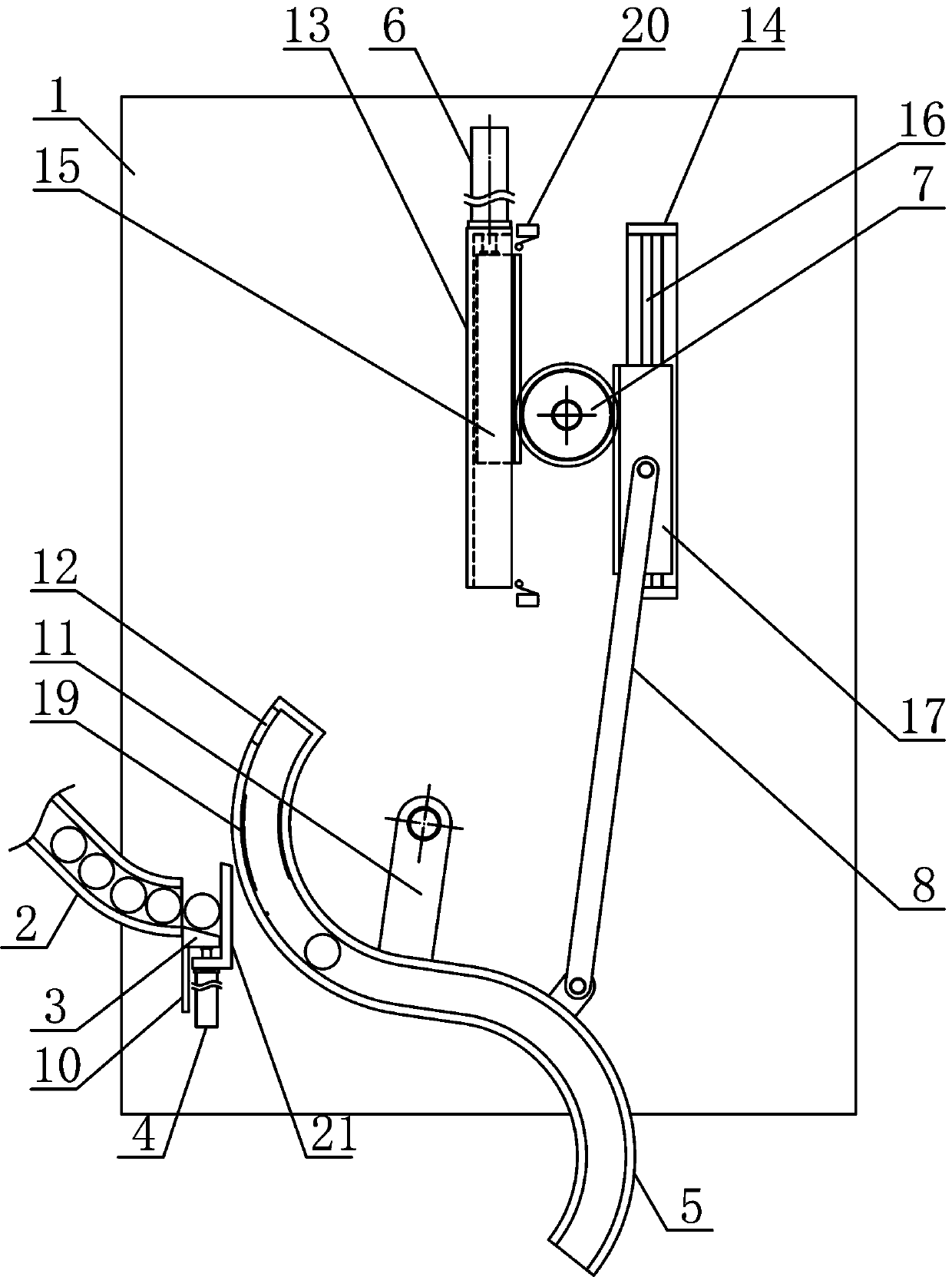
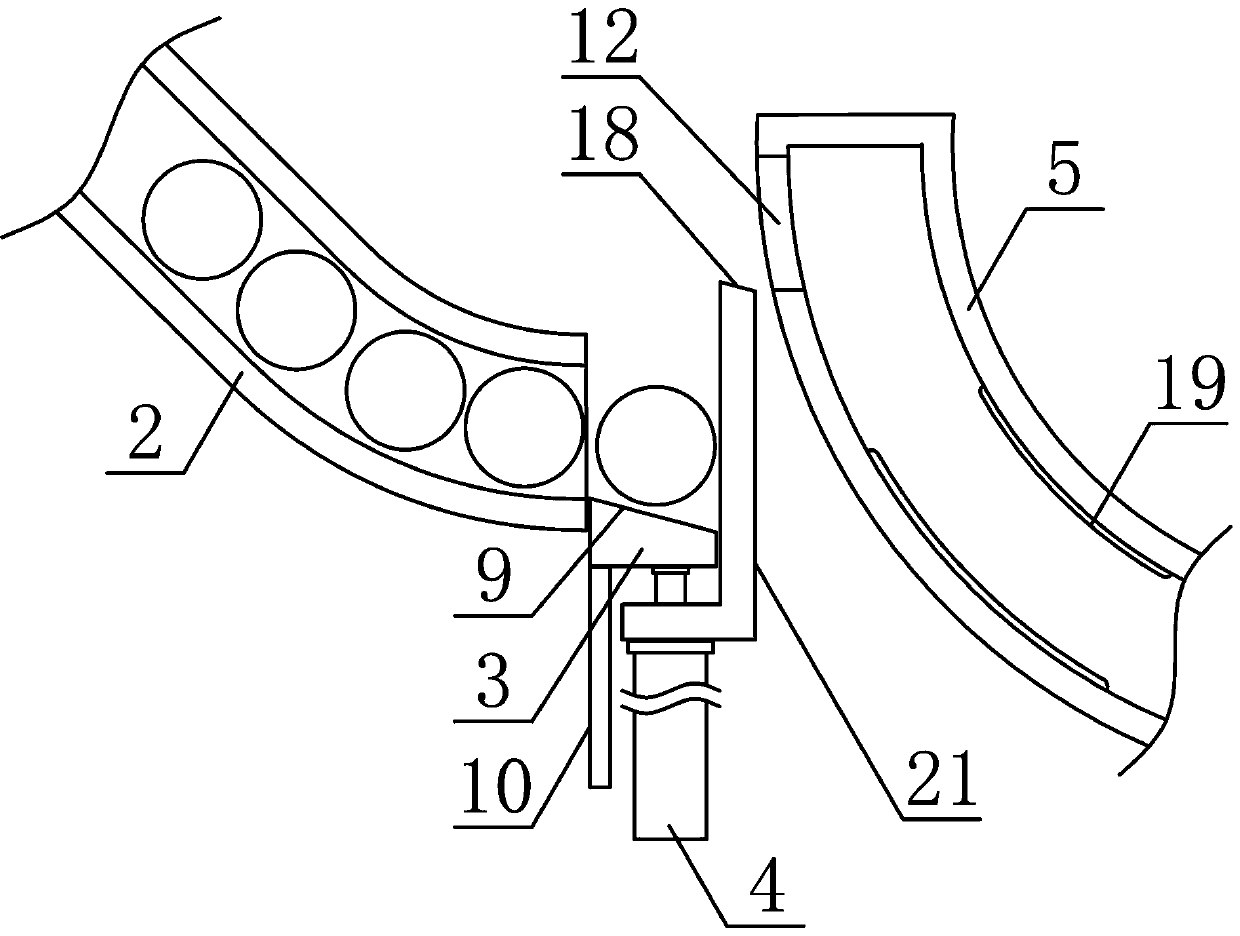
[0015] like figure 1 , figure 2 and image 3 As shown, a metal ball automatic feeding mechanism of the present invention includes a ball feeding support 1, a feeding pipe 2, a lifting push plate 3, a pushing cylinder 4, a reciprocating swinging feeding pipe 5, a swinging pipe adjusting cylinder 6, a reciprocating Rotate the gear 7 and push tube reciprocating connecting rod 8, the conveying material pipe 2 is fixedly arranged on the lower side of the ball material transfer bracket 1 obliquely downward, and the reciprocating swing material tube 5 is arranged on the ball material transfer bracket 1 on the side of the conveying material tub...


PUM


Abstract

The invention discloses an automatic metal ball conveying mechanism, and belongs to the field of processing conveying device. A reciprocating swing material pipe is arranged on a ball conveying bracket on one side of a material conveying pipe. A lifting push plate is fixedly arranged at the output end of a pushing air cylinder on the lower side of a pushing bracket; a material guide rotating seatabove the reciprocating swing material pipe is rotationally connected to the ball conveying bracket; the upper side of the reciprocating swing material pipe is rotationally connected with a reciprocating rotating gear; a main rack bracket and an auxiliary rack bracket are fixedly arranged on the parts, on the two sides of the reciprocating rotating gear, of the ball conveying bracket respectively,a main lifting rack is arranged in the main rack bracket in a sliding mode, an auxiliary lifting rack is arranged on a lifting guide rod in a sliding mode, and a push pipe reciprocating connecting rod is arranged between the auxiliary lifting rack and the reciprocating swing material pipe. The automatic metal ball conveying mechanism is reasonable in structural design, metal balls can be efficiently, stably, accurately and smoothly guided and conveyed one by one, the automation degree is high, and the processing and using requirements are met.

Description

technical field [0001] The invention belongs to the field of mechanical processing transmission equipment, in particular to a metal ball automatic material transmission mechanism. Background technique [0002] Mechanical workpieces are single parts that make up machinery and machines that cannot be separated. It plays an important role in the automation industry. Mechanical workpieces include the connection of parts, supporting parts, lubricating lubrication systems and sealing parts. Components, parts of the transmission system that transmit motion and energy, there are many types of workpieces, and shaft sleeve workpieces are especially widely used in industrial production and mechanical equipment. The main function of shaft sleeve workpieces on mechanical equipment is axial positioning, Dustproof, sealing and torque transmission, during the manufacturing and processing of shaft sleeve workpieces, it is necessary to place multiple balls evenly on the outside of the shaft t...

Claims


Application Information

Patent Timeline
Patent Type & Authority Applications(China)
IPC IPC(8): B65G47/74B65G47/52
CPCB65G47/52B65G47/74
Inventor 朱啸天
Owner 桐乡市红旗塑料包装袋厂
Why Eureka
Try Eureka