
Analysis and evaluation method for structural evolution of DNAPL contaminated cohesive soil

A technology for analysis, evaluation and structural evolution, which is applied in the fields of material analysis, permeability/surface area analysis, suspension and porous material analysis, etc. It can solve the problem of inability to judge the impact of pollutant migration due to changes in the microstructure of cohesive soils, and the low accuracy of geotechnical tests , secondary pollution prevention and control is difficult and other issues

Pending Publication Date: 2020-04-14
SHANGHAI GEOTECHN INVESTIGATIONS & DESIGN INST
View PDF0 Cites 3 Cited by
  • Summary
  • Abstract
  • Description
  • Claims
  • Application Information

AI Technical Summary

Problems solved by technology

Although the conventional physical and mechanical parameters of cohesive soils before and after pollution can be obtained through geotechnical tests, due to the low precision of geotechnical tests and the difficulty of secondary pollution prevention and control, it is impossible to distinguish the microstructural changes of cohesive soils polluted by DNAPL.
However, the soil testing in the environmental field only obtains the degree of pollution of clayey soil, and cannot judge the microstructural changes of clayey soil after being polluted by DNAPL and its impact on the migration of pollutants.

Method used


Image

  • Analysis and evaluation method for structural evolution of DNAPL contaminated cohesive soil
  • Analysis and evaluation method for structural evolution of DNAPL contaminated cohesive soil
  • Analysis and evaluation method for structural evolution of DNAPL contaminated cohesive soil

Examples


Embodiment

[0033] Embodiment: This embodiment specifically relates to an analysis and evaluation method for the structural evolution of DNAPL polluted cohesive soil. The analysis and evaluation method mainly includes the following steps in combination with examples:

[0034] (Step 1) Determine the basic environmental data of the target site, which includes environmental hydrogeological conditions and soil and groundwater environmental monitoring results.

[0035] (Step 2) According to the basic environmental data, collect undisturbed soil samples in the target soil layer in the target site, and use the photoionization detector PID to conduct rapid screening to ensure that undisturbed soil samples of non-polluted clay soil and DNAPL pollution are collected Cohesive soil undisturbed soil sample;

specific example

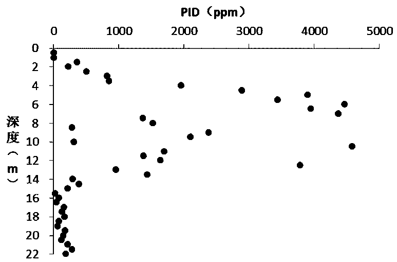
[0036] As a specific example, the sampling depth of the undisturbed non-polluted soil and DNAPL-contaminated soil is 22.3m, and the photoionization detector PID is used for rapid screening and detection every 0.5m, such as figure 1 shown;


PUM


Abstract

The invention discloses an analysis and evaluation method for structural evolution of DNAPL contaminated cohesive soil. The method comprises the following steps: determining environmental basic data of a target site; collecting a pollution-free cohesive soil undisturbed soil sample and a DNAPL polluted cohesive soil undisturbed soil sample in the target soil layer; respectively cutting the obtained undisturbed soil sample into pollution-free cohesive soil particles and DNAPL polluted cohesive soil particles with sizes required by an electron microscope scanning test and a mercury injection test, and carrying out freeze drying; then carrying out an electron microscope scanning test on the pollution-free cohesive soil particles and the DNAPL polluted cohesive soil particles; carrying out a mercury injection experiment on the freeze-dried pollution-free cohesive soil particles and DNAPL polluted cohesive soil particles; and according to the results of an electron microscope scanning testand a mercury injection test, analyzing the microstructure change of cohesive soil so as to evaluate influence of the cohesive soil on pollutant migration. The method has the advantages that the cohesive soil before and after DNAPL pollution is studied through electron microscope scanning and mercury injection experiments, and the method has significance in mastering microstructure evolution and migration characteristic changes caused by interaction of the cohesive soil and organic pollutants.

Description

technical field [0001] The invention belongs to the technical field of environmental rock and soil, and in particular relates to an analysis and evaluation method for structural evolution of DNAPL polluted cohesive soil. Background technique [0002] The prevention and control of soil and water pollution has received unprecedented attention, among which organic pollution is the most common type. The more permeable the soil layer, the easier it is for organic pollutants to migrate. The groundwater level in the Yangtze River Delta region is buried shallowly, and the shallow part is usually dominated by saturated cohesive soil, which has poor permeability in the natural state. It is generally believed that organic pollution is mainly concentrated within the shallow 10m range. However, in recent years, some industrial polluted sites in Shanghai have shown that , the maximum migration depth of organic pollutants, especially heavy non-aqueous phase organic matter (DNAPL) pollutan...

Claims


Application Information

Patent Timeline
IPC IPC(8): G01N23/2251G01N23/2202G01N15/08G01N1/28G01N1/42
CPCG01N23/2251G01N23/2202G01N15/082G01N15/088G01N1/28G01N1/42G01N2015/0833
Inventor 许丽萍李韬沈超吴育林梁颖
Owner SHANGHAI GEOTECHN INVESTIGATIONS & DESIGN INST
Learn More