Combined locomotive power supply cabinet

A power cabinet and combined technology, which is applied in the direction of electrical components, substation/power distribution device shell, substation/switch layout details, etc., can solve the problems of locomotive power cabinet without heat dissipation device, circuit blown, etc., and achieve rapid heat dissipation , the effect of preventing burnout

Pending Publication Date: 2020-04-14
GUANGDONG TECHN COLLEGE OF WATER RESOURCES & ELECTRIC ENG
View PDF0 Cites 4 Cited by
  • Summary
  • Abstract
  • Description
  • Claims
  • Application Information

AI Technical Summary

Problems solved by technology

[0003] The locomotive power cabinet generally adopts the natural heat dissipation method; in hot summer, the heat generated by the power supply in the locomotive power cabinet is difficult to dissipat

Method used


Image

  • Combined locomotive power supply cabinet
  • Combined locomotive power supply cabinet
  • Combined locomotive power supply cabinet

Examples


Example Embodiment

[0025] The technical solutions in the embodiments of the present invention will be clearly and completely described below in conjunction with the accompanying drawings in the embodiments of the present invention. Obviously, the described embodiments are only a part of the embodiments of the present invention, rather than all the embodiments. Based on the embodiments of the present invention, all other embodiments obtained by those of ordinary skill in the art without creative work shall fall within the protection scope of the present invention.

[0026] In the description of the present invention, it should be understood that the terms "center", "longitudinal", "transverse", "length", "width", "thickness", "upper", "lower", "front", " "Back", "Left", "Right", "Vertical", "Horizontal", "Top", "Bottom", "Inner", "Outer", "Clockwise", "Counterclockwise" and other directions or The positional relationship is based on the position or positional relationship shown in the drawings, and ...


PUM


Abstract

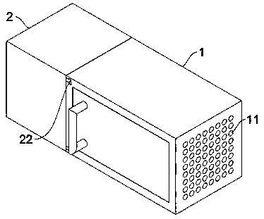
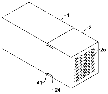
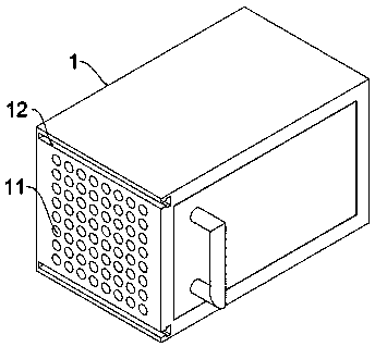
The invention relates to the technical field of locomotive power supply cabinets, and especially relates to a combined locomotive power supply cabinet which comprises a power supply cabinet. A plurality of first through holes are arranged in a left side and a right side of the power supply cabinet, T-shaped grooves are arranged above and below the first through holes, shells are arranged on one sides of the two T-shaped grooves, and a motor cavity is arranged in the side, close to the power supply cabinet, of each shell. T-shaped plates are arranged above and below the motor cavity, a second cylindrical groove is arranged in one end, close to the T-shaped plates, of one side of the shell, and a rectangular through groove is arranged in one side of the second cylindrical groove. A spring and a fixed column are arranged in the second cylindrical groove from inside to outside. A sliding block is arranged on the fixed column. A motor is arranged in the motor cavity, and an output shaft ofthe motor is provided with fan blades. Through arrangement of the shells, the motor cavity, the T-shaped plates, the second cylindrical groove, the spring, the fixing column, the motor and the fan blades, the shells can be fixed to one side of the power supply cabinet, the output shaft of the motor in the motor cavity drives the fan blades to rotate and blow air, and heat energy generated by a power supply in the power supply cabinet is rapidly dissipated.

Description

Technical field [0001] The invention relates to the technical field of locomotive power supply cabinets, in particular to a combined locomotive power supply cabinet. Background technique [0002] The locomotive power cabinet is the control center that commands the reasonable distribution of electrical energy for various components in the power supply line. It is the control link that reliably receives the upper power supply and correctly feeds the load electrical energy. It is also the key to obtaining the user's satisfaction with the power supply quality and improving the power supply of the powered locomotive. The operation reliability of the cabinet is the goal of creating a high-quality project. The locomotive power cabinet is generally assembled in a closed or semi-enclosed metal cabinet or on a screen according to the electrical wiring requirements. The switchgear, measuring instruments, protective appliances and auxiliary equipment are assembled Low-voltage locomotive powe...

Claims


Application Information

Patent Timeline
IPC IPC(8): H02B1/30H02B1/56
CPCH02B1/30H02B1/306H02B1/565
Inventor 邵忠良韩琳匡畅
Owner GUANGDONG TECHN COLLEGE OF WATER RESOURCES & ELECTRIC ENG
Why Eureka
Try Eureka