
Electric cooking appliance

A technology for electrical appliances and cooking chambers, which is applied in the direction of steam cooking utensils, cooking utensils, roasters/barbecue grids, etc., which can solve problems that affect cooking effects, human body hazards, and electrical appliances are difficult to oil, so as to improve cooking effects and avoid hazards , the effect of reducing waiting time

Active Publication Date: 2020-04-17
GUANGDONG MIDEA KITCHEN APPLIANCES MFG CO LTD +1
View PDF11 Cites 9 Cited by
  • Summary
  • Abstract
  • Description
  • Claims
  • Application Information

AI Technical Summary

Problems solved by technology

Among them, water vapor will be sprayed directly when the door is opened after cooking, which is harmful to the human body, and after the water vapor condenses, a large amount of water will form, which needs to be cleaned with a rag; It is harmful, and the residual oil fume will make the inside of the appliance accumulate oil stains that are difficult to clean, and produce bad taste; and the taste of the food itself will also remain inside the appliance. Over time, different foods are easy to smell during the cooking process, affecting cooking Effect

Method used


Image

  • Electric cooking appliance
  • Electric cooking appliance
  • Electric cooking appliance

Examples


Embodiment 1

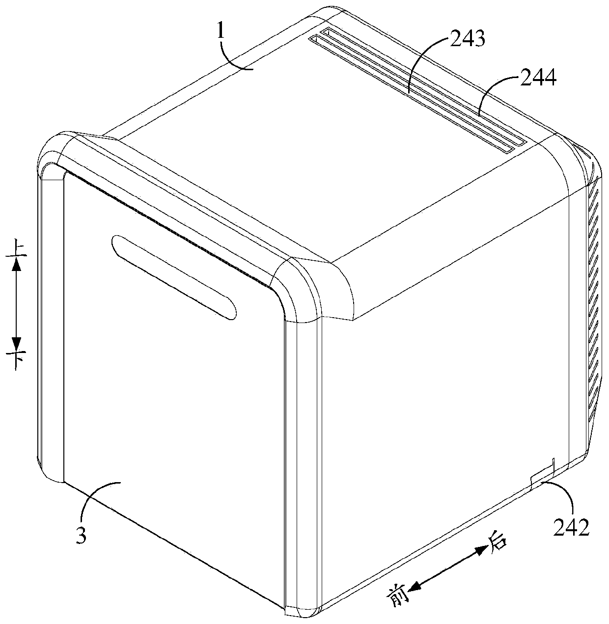
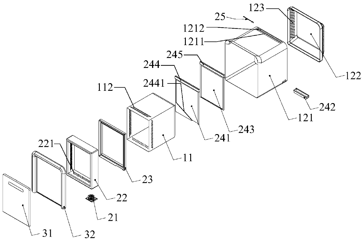
[0072] A cooking appliance, comprising: an appliance main body 1 and a deodorizing device.

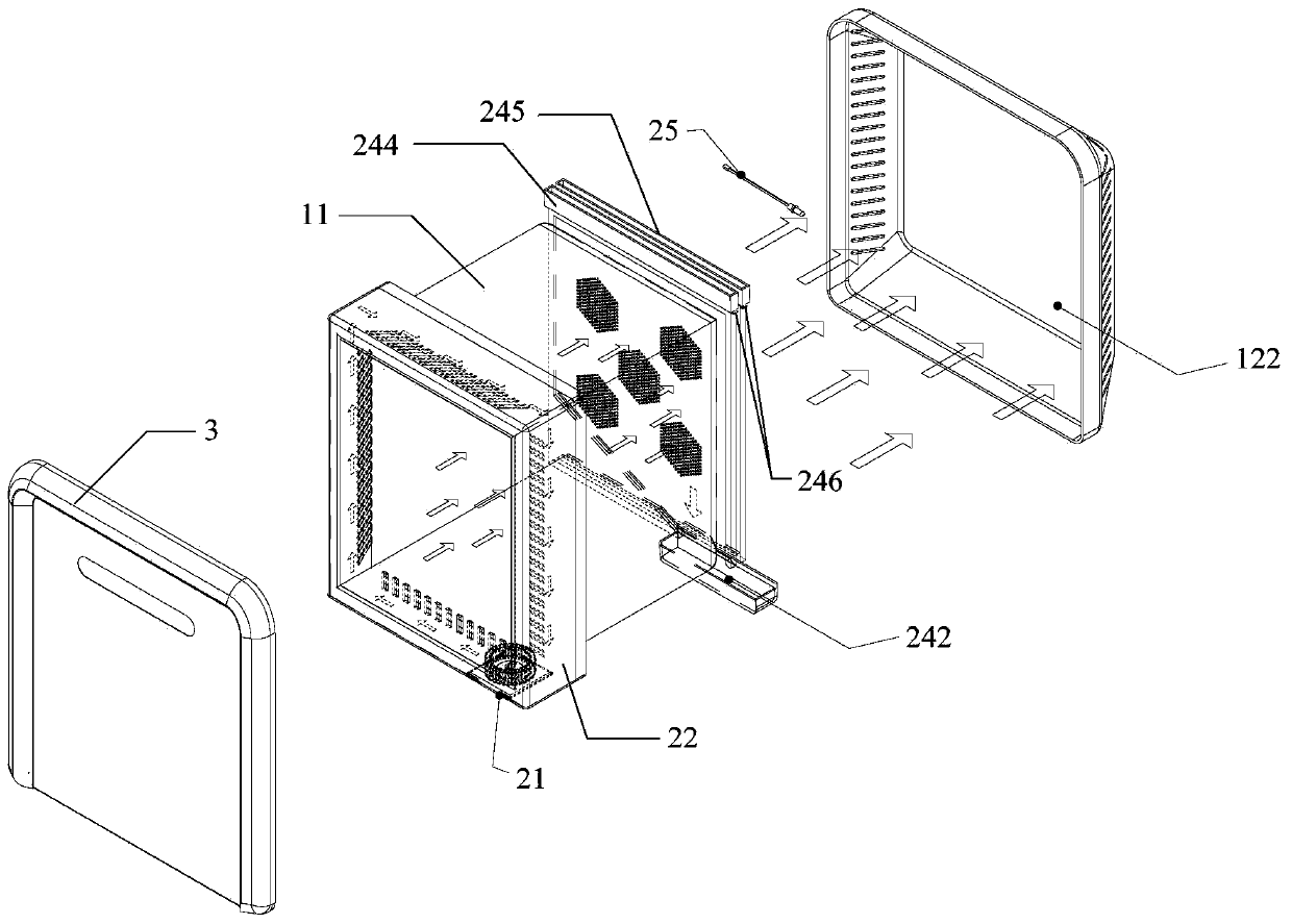
[0073] Specifically, a cooking cavity 111 is provided in the electrical appliance main body 1, such as image 3 shown.

[0074] The deodorizing device is arranged in the main body 1 of the electrical appliance, and is provided with an airflow passage connecting the cooking cavity 111 and the external environment, for dissipating the odor through the airflow passage, such as image 3 with Figure 4 As shown, to deodorize the cooking cavity 111.

[0075] In the cooking appliance provided by the present invention, a deodorizing device is added in the main body 1 of the appliance. Since the deodorizing device is provided with an airflow channel communicating with the cooking cavity 111 and the external environment, the water vapor in the cooking cavity 111, The smell of the food itself and the smell of the food itself are discharged into the external environment to play an effective deo...

Embodiment 2

[0091] The difference from the first embodiment is that: the outlet of the air flow channel is provided with a ventilation device.

[0092] An exhaust device is provided at the outlet of the air flow channel, and the gas in the cooking cavity 111 will flow out under the drive of the exhaust device, thereby realizing the deodorization effect.

Embodiment 3

[0094] The difference from Embodiment 1 lies in: the negative pressure device.

[0095] If a negative pressure device is installed at the outlet of the airflow channel, the gas in the cooking cavity 111 will flow out under the negative pressure, so as to realize the deodorization effect.


PUM


Abstract

The invention provides an electric cooking appliance, which comprises an electric appliance main body in which a cooking cavity is formed; and an odor removal device arranged in the electric appliancemain body, provided with an airflow channel for communicating the cooking cavity with the external environment, and used for removing odor from the cooking cavity through the airflow channel. The odor removal device is provided with the airflow channel for communicating the cooking cavity with the external environment, so that after cooking is finished, water vapor in the cooking cavity, the taste of food, oil fume and the like can be exhausted to the external environment, effective odor removing effect is achieved, various smells such as water vapor, oil fume and the taste of food are prevented from being accumulated in the cooking cavity, the body health of a user is further facilitated, and the cleanliness and the cooking effect of the electric cooking appliance are also improved. Besides, compared with a scheme of arranging an internal circulation channel in the electric appliance main body for odor removal, the scheme is beneficial to improving the odor removal speed, reducing the waiting time of a user, simplifying the product structure and reducing the product size.

Description

technical field [0001] The invention relates to the technical field of kitchen appliances, in particular to a cooking appliance. Background technique [0002] Current cooking appliances produce many odors during the cooking process, including the taste of the food itself, water vapor and oily fumes. Among them, water vapor will be sprayed directly when the door is opened after cooking, which is harmful to the human body, and after the water vapor condenses, a large amount of water will form, which needs to be cleaned with a rag; Harmful, and the residual oil fume will make the accumulation of oil stains inside the appliance that are difficult to clean, and produce bad taste; and the taste of the food itself will also remain inside the appliance. Over time, different foods are easy to smell during the cooking process, affecting cooking Effect. Contents of the invention [0003] In order to solve at least one of the above technical problems, the object of the present inven...

Claims


Application Information

Patent Timeline
Patent Type & Authority Applications(China)
IPC IPC(8): A47J27/04A47J36/38A47J37/06F24C15/20
CPCA47J27/04A47J36/38A47J37/0629A47J37/0664F24C15/2035A47J2027/043
Inventor 崔东海钟昌理曹庆刚李杰罗锦玲杨康
Owner GUANGDONG MIDEA KITCHEN APPLIANCES MFG CO LTD
Learn More