Spindle structure and machine tool with it

A spindle and drive structure technology, applied in the direction of manufacturing tools, metal processing machinery parts, metal processing equipment, etc., can solve the problems of poor positioning accuracy, etc., to solve the problem of poor positioning accuracy, reduce the transmission chain, and fast braking response Effect

Active Publication Date: 2021-02-09
GREE ELECTRIC APPLIANCES INC
View PDF9 Cites 0 Cited by
  • Summary
  • Abstract
  • Description
  • Claims
  • Application Information

AI Technical Summary

Problems solved by technology

[0004] The main purpose of the present invention is to provide a spindle structure and a machine tool with it, so as to solve the technical problem that the spindle structure in the prior art has poor positioning accuracy during braking

Method used


Image

  • Spindle structure and machine tool with it
  • Spindle structure and machine tool with it
  • Spindle structure and machine tool with it

Examples


Embodiment Construction

[0028] It should be noted that, in the case of no conflict, the embodiments in the present application and the features in the embodiments can be combined with each other. The present invention will be described in detail below with reference to the accompanying drawings and examples.

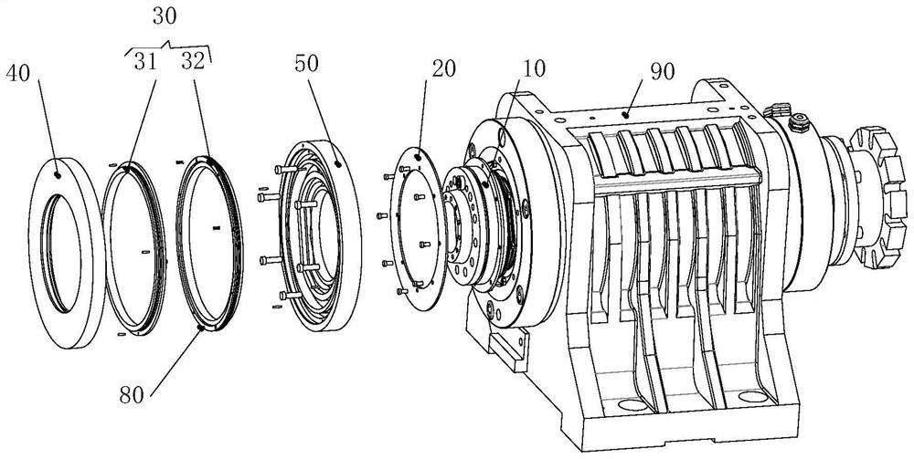
[0029] Such as Figure 1 to Figure 7 As shown, the embodiment of the present invention provides a spindle structure, the spindle structure includes a shaft core 10, a brake disc 20 and a brake assembly 30, the shaft core 10 is rotatably set; the brake disc 20 is set on the shaft core 10 so that the shaft core 10 drives the brake disc 20 to rotate, and the outer edge of the brake disc 20 protrudes beyond the outer edge of the shaft core 10 . The brake assembly 30 includes a first brake part 31 and a second brake part 32, the first brake part 31 is movably arranged on one side of the brake disc 20, and the second brake part 32 is movably arranged on the brake disc 20. The other side of the movi...


PUM


Abstract

The invention provides a spindle structure and a machine tool with the same. The spindle structure comprises a spindle core, a brake disc and a brake assembly, wherein the brake disc is arranged on the spindle core so that the brake disc is driven to rotate by the spindle core, and the brake disc is arranged in a manner of being bulged out of the spindle core; the brake assembly comprises a firstbrake part and a second brake part, the first brake part is movably arranged at one side of the brake disc, and the second brake part is movably arranged at the other side of the brake disc; the brakeassembly has a brake state and an avoiding state, and when the brake assembly is in the brake state, the first brake part and the second brake part are arranged on the brake disc in a clamping manner, so that the spindle core stops rotating; and when the brake assembly is in the avoiding state, the first brake part and the second brake part are arranged in a manner of being spaced from the brakedisc to avoid the brake disc; and the spindle core is provided with a drive section and a connection section which are oppositely arranged, the connection section is used for being connected with an element to be connected, and the brake assembly and the brake disc are arranged on the connection section. The technical problem of low location accuracy of a spindle structure in the prior art duringbrake is solved.

Description

technical field [0001] The invention relates to the technical field of numerical control machine tools, in particular to a spindle structure and a machine tool with the same. Background technique [0002] At present, in the actual processing of machine tools such as turn-milling compound and multi-axis machining centers, not only the spindle is required to provide rotating turning action, but also the spindle core is often required to brake the clamped parts to realize the processing of another spindle (such as milling) , so machine tools such as turn-milling machine tools and multi-axis machining centers require the spindle to have the spindle braking function. [0003] At present, the more common brake structure on the market is an independent clamp, which is generally placed at the rear end of the main shaft to clamp the brake disc at the rear end of the main shaft. The biggest disadvantages of this structure are: first, it is difficult to debug the installation position...

Claims


Application Information

Patent Timeline
Patent Type & Authority Patents(China)
IPC IPC(8): B23B19/02
CPCB23Q1/70
Inventor 钟成堡耿继青何圳涛刘永连王攀叶俊奇宋健
Owner GREE ELECTRIC APPLIANCES INC
Why Eureka
Try Eureka