Process for machining clutch booster shell

A processing technology and booster technology, applied in clutches, mechanical equipment, etc., can solve the problems of hindering oil flow, reducing sealing and service life, scraping the push rod hole, etc., to improve the smoothness, reduce the probability of wear, prolong the The effect of service life

Active Publication Date: 2020-04-17
ZHUJI WANSHENG MACHINERY
View PDF5 Cites 2 Cited by
  • Summary
  • Abstract
  • Description
  • Claims
  • Application Information

AI Technical Summary

Problems solved by technology

[0004] The above-mentioned technical solution has the following defects: in the process of opening the connecting hole, burrs will be generated at both ends of the connecting hole, which will affect both the push rod hole and the oil inlet. On the one hand, the burrs may wear the push rod and reduce the seal. Sex, and the push rod may scrape off the burr and move in the push rod hole, thereby scratching the push rod hole, reducing the sealing and service life; on the other hand, the burr will hinder the circulation of oil, and when the burr is washed off by the oil , will also wear down the subsequent structure

Method used


Image

  • Process for machining clutch booster shell
  • Process for machining clutch booster shell
  • Process for machining clutch booster shell

Examples


Embodiment Construction

[0049] The present invention will be described in further detail below in conjunction with the accompanying drawings.

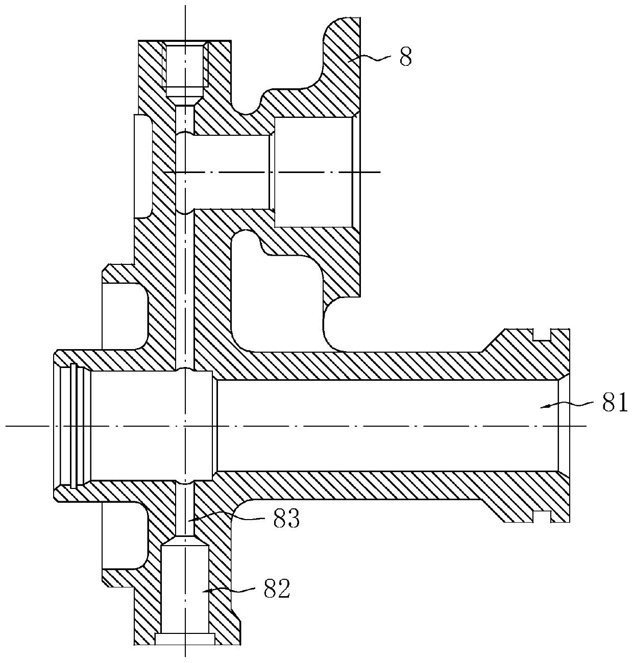
[0050] A kind of processing technology of clutch booster shell, refer to figure 1 , including the following steps:

[0051] S1: Prepare shell blank 8;

[0052] S2: 8-car outer circle, end face and chamfering of the shell original blank by CNC lathe;

[0053] S3: 8 grooves for the shell blank processed by S2 through CNC lathe;

[0054] S4: Carry the oil inlet 82 of the shell blank 8 processed in S3 by a CNC lathe, and carve the tooth groove on the end face of the oil inlet 82;

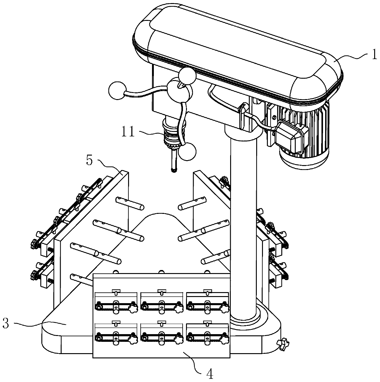
[0055] S5: Drill the connecting hole 83 on the shell blank 8 processed in S4 by bench drill, make the oil inlet 82 communicate with the push rod hole 81, and deburr the opening of the connecting hole 83;

[0056] S6: Process the piston hole and installation hole on the shell blank 8 processed in S5 through the drilling and tapping center, the piston hole and the installation hole a...


PUM


Abstract

The invention relates to a process for machining a clutch booster shell, and relates to the technical field of clutch boosters. The process comprises the steps of 1, preparing a shell blank; 2, turning an outer circle, an end face and a chamfer; 3, turning a groove; 4, turning an oil inlet; 5, drilling a connecting hole; 6, machining a piston hole and a mounting hole; 7, machining an exhaust screwhole and an air bleed screw hole; 8, carrying out reaming; 9, carrying out honing; and 10, carrying out cleaning, wherein the orifice of the connecting hole is deburred through a bench drill in the step 5. According to the process for machining the clutch booster shell, the connecting hole is deburred through the bench drill, so that the junction of the connecting hole and the oil inlet and the junction of the connecting hole and a push rod hole are relatively smooth, and in subsequent use, a push rod is prevented from being scratched due to burrs and the sealing performance is not affected;and the oil flows smoothly at the oil inlet and the connecting hole, the situation that burrs enter the oil is avoided, and the service life is prolonged.

Description

technical field [0001] The invention relates to the technical field of clutch boosters, in particular to a processing technology for a clutch booster housing. Background technique [0002] In a car with a hydraulically operated clutch, the clutch booster is usually used as the main component of the clutch hydraulically operated booster mechanism, which directly affects the working efficiency of the clutch. The clutch booster is generally installed between the clutch and the clutch master cylinder to provide auxiliary power when the clutch is disengaged or engaged. [0003] Clutch boosters generally include a housing and components installed in the housing. During the production of the housing, holes, grooves and chamfering will be performed by CNC machine tools, machining centers and other equipment. In the casing, the push rod hole and the oil inlet are necessary holes, and a connecting hole will be opened through the equipment to connect the push rod hole and the oil inle...

Claims


Application Information

Patent Timeline
IPC IPC(8): B23P15/00F16D48/04
CPCB23P15/00F16D48/04
Inventor 陈伟平
Owner ZHUJI WANSHENG MACHINERY
Why Eureka
Try Eureka