Turnover type taking and placing mechanism

A flip-up, rotating shaft technology, applied in the direction of conveyor objects, transportation and packaging, can solve the problems of increasing the complexity of equipment assembly, lack of flipping function, increasing equipment manufacturing costs, etc., to reduce equipment complexity and manufacturing costs, Improve the efficiency of suction and turning operations, and the effect of exquisite design

Pending Publication Date: 2020-04-17
SUZHOU RS TECH
View PDF0 Cites 1 Cited by
  • Summary
  • Abstract
  • Description
  • Claims
  • Application Information

AI Technical Summary

Problems solved by technology

[0003] The existing pick-and-place mechanism can only realize the suction or grasping action of the material, and lacks the flipping function. For operations that need to turn the material over a certain angle, it often requires at least two sets of pick-and-place mechanisms to cooperate with each other. This aspect increases The volume of equipment space increases the complexity of equipment assembly, resulting in low efficiency of pick-and-place and turning, and on the other hand, it also increases equipment manufacturing costs

Method used


Image

  • Turnover type taking and placing mechanism
  • Turnover type taking and placing mechanism
  • Turnover type taking and placing mechanism

Examples


Embodiment Construction

[0036] The technical solutions in the embodiments of the present invention will be clearly and completely described below in conjunction with the accompanying drawings in the embodiments of the present invention. Obviously, the described embodiments are only part of the embodiments of the present invention, not all of them. Based on the implementation methods in the present invention, all other embodiments obtained by persons of ordinary skill in the art without making creative efforts belong to the protection scope of the present invention.

[0037] In the drawings, the shapes and dimensions may be exaggerated for clarity, and the same reference numerals will be used throughout to designate the same or like parts.

[0038] In the following description, terms such as center, thickness, height, length, front, back, rear, left, right, top, bottom, upper, lower, etc. are defined with respect to the configuration shown in each drawing , in particular, "height" is equivalent to the...


PUM


Abstract

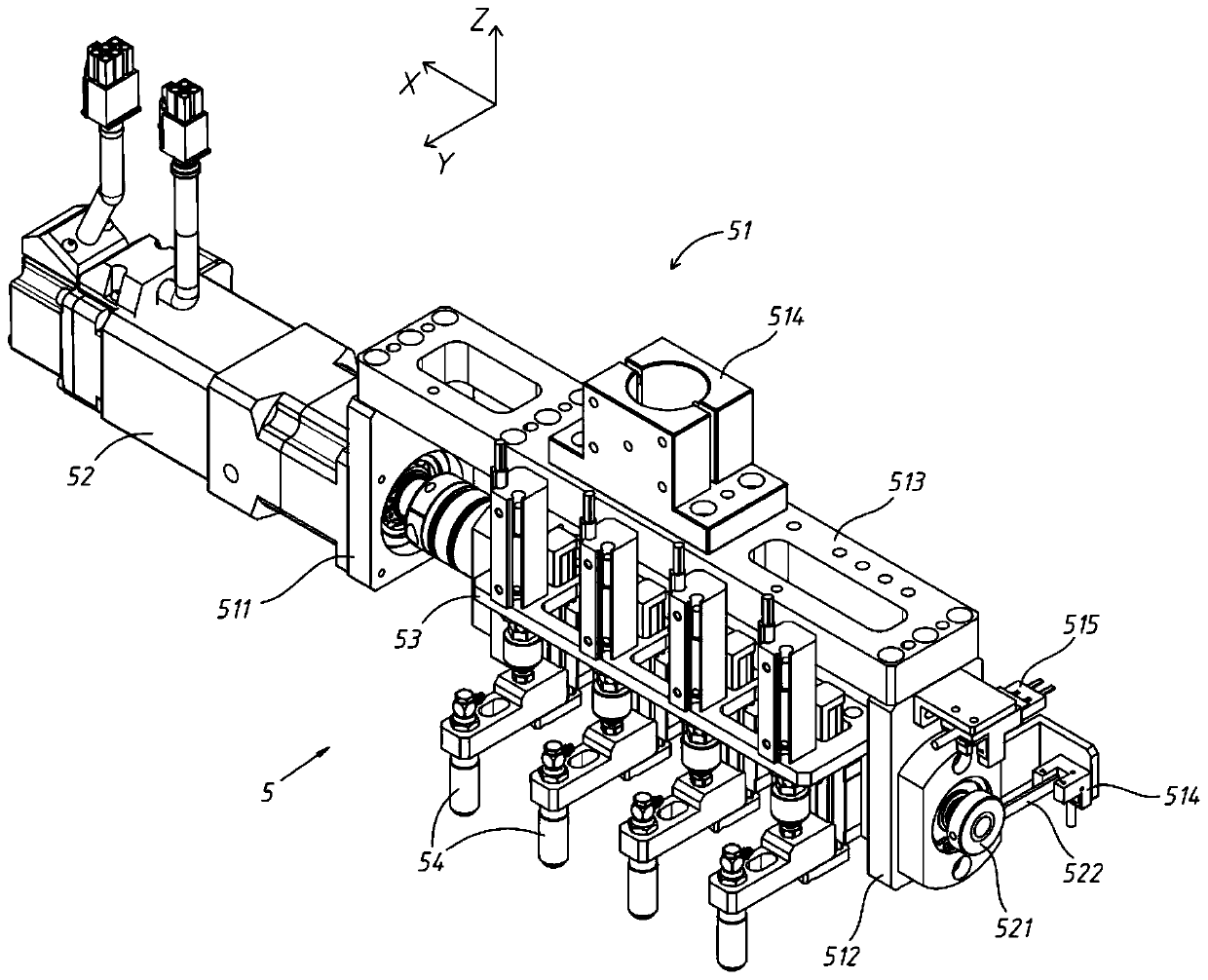
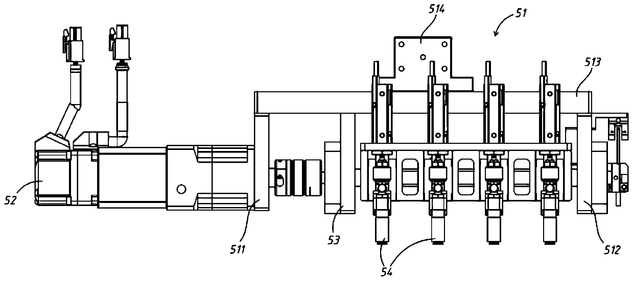
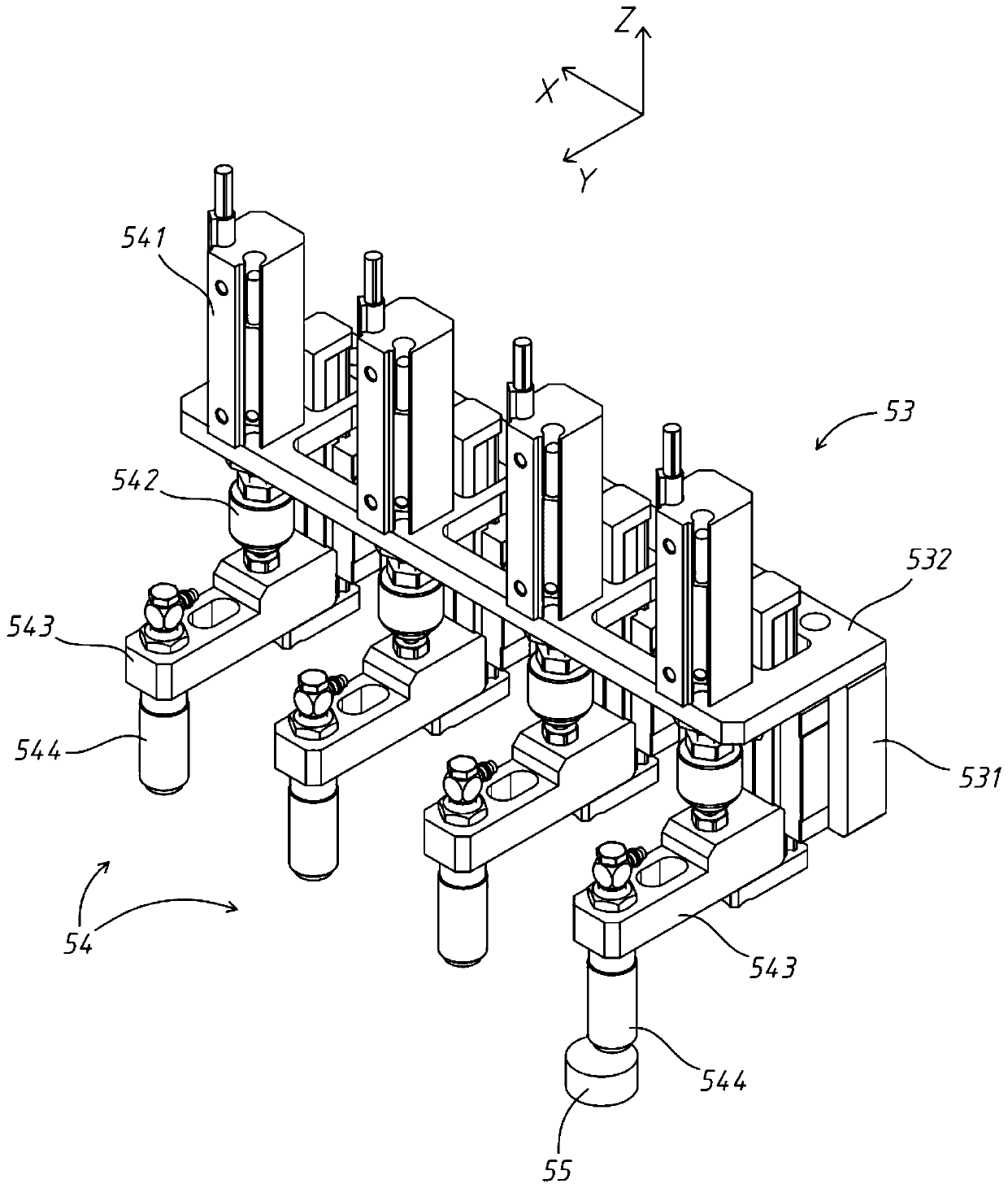
The invention discloses a turnover type taking and placing mechanism, which comprises a fixed mounting frame, a turnover mounting frame, at least one group of taking and placing assembly and a turnover driver, wherein the turnover mounting frame is arranged in the fixed mounting frame; the at least one group of taking and placing assembly is mounted in the turnover mounting frame; the turnover driver is arranged on the fixed mounting frame, the power output end of the turnover driver is in transmission connection with the turnover mounting frame; at least one lifting guide rail extending in the vertical direction is connected into the turnover mounting frame in a sliding mode; each taking and placing assembly is fixedly connected with the corresponding lifting guide rail; and the turnovermounting frame is driven by the turnover driver to do reciprocating turnover motion between 0 degree and 90 degrees. Thus, materials can be overturned within a certain angle range after being sucked,so that the actual production requirement is met, the structure is compact, the design is ingenious, the equipment complexity and the manufacturing cost are reduced, and the sucking and turnover operation efficiency is improved.

Description

technical field [0001] The invention relates to the field of non-standard automation, in particular to a flip-type pick-and-place mechanism. Background technique [0002] In non-standard automation, it is well known that pick-and-place mechanisms with different structures are used to pick and place materials. In the process of researching and realizing the pick-and-place operation of materials, the inventor found that there are at least the following problems in the pick-and-place mechanism in the prior art: [0003] The existing pick-and-place mechanism can only realize the suction or grasping action of the material, and lacks the flipping function. For operations that need to turn the material over a certain angle, it often requires at least two sets of pick-and-place mechanisms to cooperate with each other. This aspect increases The volume of equipment space increases the complexity of equipment assembly, resulting in low efficiency of pick-and-place and turning, and on ...

Claims


Application Information

Patent Timeline
IPC IPC(8): B65G47/91B65G47/248
CPCB65G47/248B65G47/915
Inventor 吴加富缪磊蒋玉斌肖夕全万发
Owner SUZHOU RS TECH
Why Eureka
Try Eureka