Steam turbine independent control high-pressure main steam regulating valve

An independent control, steam turbine technology, applied in the direction of mechanical equipment, engine components, machines/engines, etc., can solve the problems of complex structure design, spray coating peeling, frequent problems, etc., achieve simple structure design, improve maintenance efficiency, and easy disassembly and maintenance Effect

Pending Publication Date: 2020-04-17
河北国源电气股份有限公司
View PDF0 Cites 1 Cited by
  • Summary
  • Abstract
  • Description
  • Claims
  • Application Information

AI Technical Summary

Problems solved by technology

The valve sleeve structure is a long structure, and the inner hole is sprayed with Stellite alloy treatment or nitriding treatment to slide with the valve stem. Due to the long valve stem, the sprayed coating falls off after long-term operation, the straightness is out of tolerance, the scale is serious, and the valve is stuck. Hysteresis is frequent
[0005] 3. During the operation of the steam turbine unit, the valve stem and the valve head are required not to rotate relative to the valve seat. Usu

Method used


Image

  • Steam turbine independent control high-pressure main steam regulating valve
  • Steam turbine independent control high-pressure main steam regulating valve
  • Steam turbine independent control high-pressure main steam regulating valve

Examples


Embodiment 1

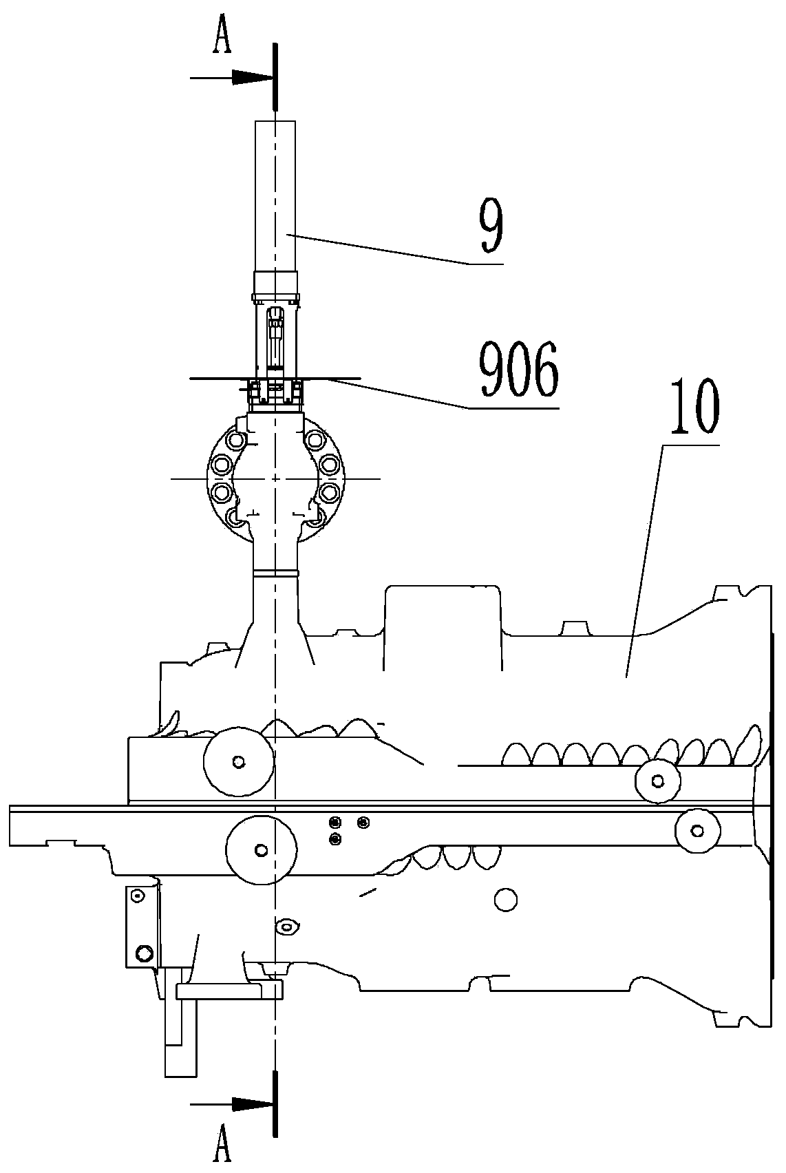
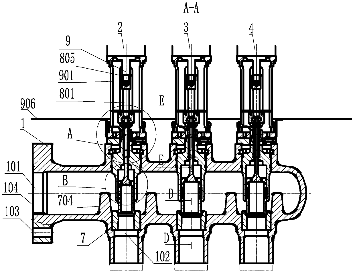
[0043] Such as Figure 1-6 As shown, a steam turbine independently controls the high-pressure main steam regulating valve, including a valve body 1, a cavity is opened inside the valve body 1, a steam inlet 101 is opened on the left end surface of the valve body 1, and the upper side of the valve body 1 is opened at intervals on the same Three guide holes of row, install valve A2, valve B3, valve C4 respectively in three guide holes, the lower side of valve body 1 offers three steam outlet holes 102, and three steam outlet holes 102 are the same as three guide holes axis relative.

[0044] The end face of the steam inlet 101 of the valve body 1 is provided with a flange integrally connected to the valve body 1, and the main steam valve is connected to the main steam valve through the bolts installed in the flange hole. Tooth-shaped sealing gasket realizes the end face sealing of the two valves. The main steam regulating valve adjusts and controls the steam input by the main ...


PUM


Abstract

The invention relates to a steam turbine independent control high-pressure main steam regulating valve. The steam turbine independent control high-pressure main steam regulating valve comprises a valve body, wherein a valve A, a valve B and a valve C which are transversely arranged and are parallel to one another are mounted on the valve body, and the three valves have the same structure; the valve body is provided with a steam inlet, three guide holes for mounting the valves are formed in the upper side, corresponding to the steam inlet, of the valve body, and three steam outlet holes coaxially opposite to the guide holes are formed in the lower side, corresponding to the steam inlet, of the valve body; each valve comprises a guide valve sleeve, a valve rod and a valve seat, the guide valve sleeve is mounted in each guide hole, the valve rod is arranged in a central through hole of each guide valve sleeve in a penetrating manner, the valve tail of the valve rod extends upwards out ofeach guide valve sleeve and is connected with a hydraulic motor through a coupler, the valve head of the valve rod is assembled at the lower part of each guide valve sleeve and is matched with the hydraulic motor to enter and exit each guide valve sleeve, and the valve seat is correspondingly arranged below each valve head and is fixed at each steam outlet hole. According to the steam turbine independent control high-pressure main steam regulating valve provided by the invention, the function of coordinating steam flow is realized through the design of combined steam valves which are independent from one another and can work in a combined manner.

Description

technical field [0001] The invention relates to the technical field of steam turbine valve equipment, in particular to a steam turbine independent control high-pressure main steam regulating valve. Background technique [0002] The steam turbine is the main equipment of the thermal power plant. The steam intake and exhaust of the steam turbine are realized through the cooperation of various valves. The high-pressure main steam regulating valve is a valve to adjust the flow of the main steam. Generally, it is installed at the back end of the main steam valve, and the number of installations is 4. They are distributed and symmetrically installed on both sides of the steam turbine, and the steam entering the high-pressure cylinder to do work is adjusted separately. Each high-pressure main steam regulating valve is provided with its own oil motor, valve body, valve stem and valve seat. The existing conventional high-pressure main steam regulating valve has the following problem...

Claims


Application Information

Patent Timeline
IPC IPC(8): F01D17/10
CPCF01D17/10
Inventor 刘运智张跃普刘敬贤徐新燕李少泽王文冉李超杨立民韩天成
Owner 河北国源电气股份有限公司
Why Eureka
Try Eureka