Ground test simulation device and method for separating device

A separation device and ground test technology, applied to jet propulsion devices, rocket engine devices, machines/engines, etc., to achieve the effects of reducing economic losses, verifying reliability, and reducing separation risks

Active Publication Date: 2020-04-17
BEIJING POWER MACHINERY INST
View PDF5 Cites 3 Cited by
  • Summary
  • Abstract
  • Description
  • Claims
  • Application Information

AI Technical Summary

Problems solved by technology

At present, there is no test device and method capable of simulating the separation device on the ground

Method used


Image

  • Ground test simulation device and method for separating device
  • Ground test simulation device and method for separating device
  • Ground test simulation device and method for separating device

Examples


Embodiment 1

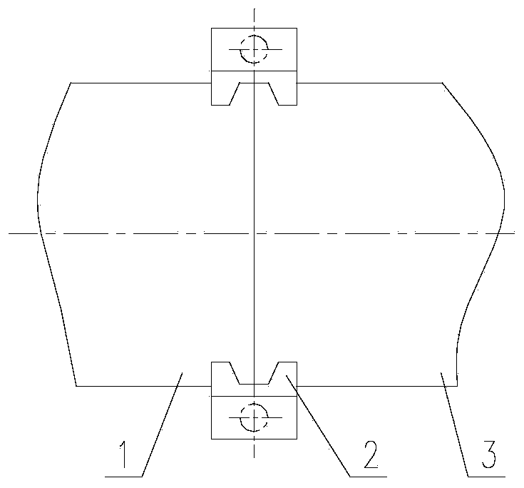
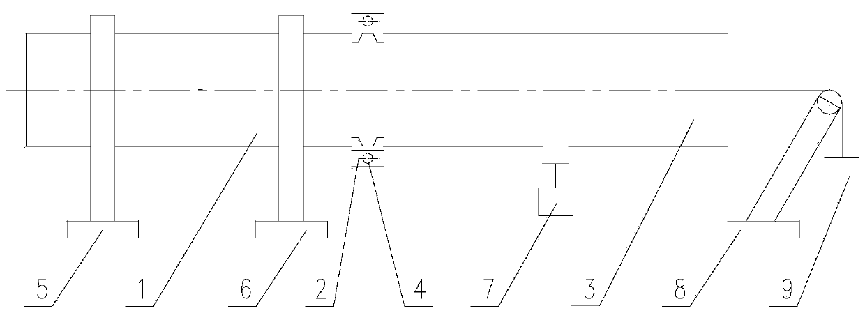
[0032] This embodiment provides a ground test simulation device for a separation device, see the attached image 3 , including: engine A1, engine B3, snap ring 2, explosion bolt 4, fixing bracket A5, fixing bracket B6, counterweight A7, roller bracket 8 and counterweight B9;

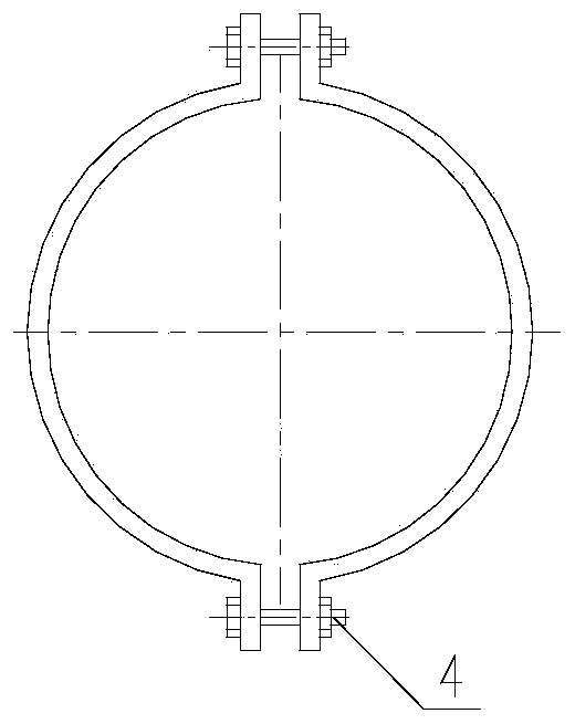
[0033] The snap ring 2 is composed of two semi-circular rings, and the two semi-circular rings are connected into a circular ring by two explosive bolts 4, or the snap ring 2 is composed of four 1 / 4 circular rings, and the four 1 / 4 circular rings are The ring is connected into a circular ring by four explosive bolts 4; the inner peripheral surface of the snap ring 2 is provided with two annular bosses; the engine A1 and the engine B3 both adopt a cylindrical hollow shell consistent with the actual engine shell shape, and the engine A1 The outer circumferential surface of the docking end with the engine B3 is processed with an annular card groove;

[0034] The snap ring 2 is set on the outside of the eng...

Embodiment 2

[0038] Since the bending moment experienced by the snap ring 2 is very small during the stage-to-stage separation of many aircraft, the bending moment experienced by the snap ring 2 can be ignored.

[0039] The ground test simulation device of a kind of separation device of present embodiment, see appendix Figure 4 , including: engine A1, engine B3, snap ring 2, explosion bolt 4, spreader 10 and counterweight C11;

[0040] The snap ring 2 is composed of two semi-circular rings, and the two semi-circular rings are connected into a circular ring by two explosive bolts 4, or the snap ring 2 is composed of four 1 / 4 circular rings, and the four 1 / 4 circular rings are The ring is connected into a circular ring by four explosive bolts 4; the inner peripheral surface of the snap ring 2 is provided with two annular bosses; the engine A1 and the engine B3 both adopt the cylindrical hollow shell of the engine, and the docking of the engine A1 and the engine B3 The outer peripheral surf...

Embodiment 3

[0044]On the basis of Example 1 or Example 2, for some engines with larger product quality and scale, use the cylindrical test piece A paired with the snap ring interface to replace the engine A1, and the cylindrical test piece A paired with the snap ring interface Part B replaces engine B3.


PUM


Abstract

The invention discloses a ground test simulation device and method for a separating device, and belongs to the technical field of separating device tests. The ground test simulation device comprises an engine A, an engine B, snap rings, explosive bolts, a supporting structure and a counterweight; each snap ring is composed of more than two arc segments, the two or more arc segments are sequentially butted to form a circular ring, and two adjacent arc segments are connected through an explosive bolt; the snap rings simultaneously sleeve outside the butt-joint end of the engine A and the engineB after coaxial butt joint, and the snap rings and the explosive bolts form the separating device; the engine A and the engine B are horizontally fixed to the ground or vertically hoisted through thesupporting structure, the counterweight is installed at the tail of the engine B through a steel wire rope, the counterweight is used for providing an axial force for the engine B, the axial force isused for simulating an axial force F born by the snap rings at the separating moment of the engine A and the engine B. According to the ground test simulation device, the process of separating the engines can be simulated truly on the ground, and the reliability of the separating device is verified.

Description

technical field [0001] The invention belongs to the technical field of separation device testing, and in particular relates to a ground test simulation device and method of a separation device. Background technique [0002] For launch vehicles, missiles and other aircraft, there are often situations where solid rocket motors are separated step by step to reduce the negative mass, making the aircraft have a longer range and a higher flight altitude, and then transport the payload to the predetermined location. At the same time, the reliability of the separation device is very important. If there is an abnormality, it may lead to abnormal attitude of the aircraft, or even the failure of the flight mission, resulting in serious economic losses. Therefore, it is necessary to verify the reliability of the separation device on the ground. At present, there is no test device and method capable of simulating the separation device on the ground. Contents of the invention [0003]...

Claims


Application Information

Patent Timeline
Patent Type & Authority Applications(China)
IPC IPC(8): F02K9/96
CPCF02K9/96
Inventor 韩江锋程恒星王玉清李嵩蒋妮裘云
Owner BEIJING POWER MACHINERY INST
Why Eureka
Try Eureka