
Cutting force automatic control main shaft reliability test device and test method

A technology of automatic control device and test device, which is applied in the direction of measuring device, testing of mechanical components, testing of machine/structural components, etc., which can solve problems such as expensive equipment manufacturing costs, inability to accurately simulate the real working conditions of the spindle, and complex control methods , to achieve the effect of verifying the reliability of

Active Publication Date: 2017-02-22
JILIN UNIV
View PDF7 Cites 25 Cited by
  • Summary
  • Abstract
  • Description
  • Claims
  • Application Information

AI Technical Summary

Problems solved by technology

[0003] The technical problem to be solved by the present invention is to overcome the problems existing in the prior art that the real working conditions of the spindle cannot be accurately simulated, the control method is complicated, and the equipment manufacturing cost is expensive, and a spindle reliability test device and test method for automatic control of cutting force are provided.

Method used


Image

  • Cutting force automatic control main shaft reliability test device and test method
  • Cutting force automatic control main shaft reliability test device and test method
  • Cutting force automatic control main shaft reliability test device and test method

Examples


specific Embodiment

[0125] The spindle reliability test device and method of the present invention are mainly composed of two parts, namely the spindle reliability test device part and the spindle reliability test method part.

[0126] 1. Spindle reliability test device part

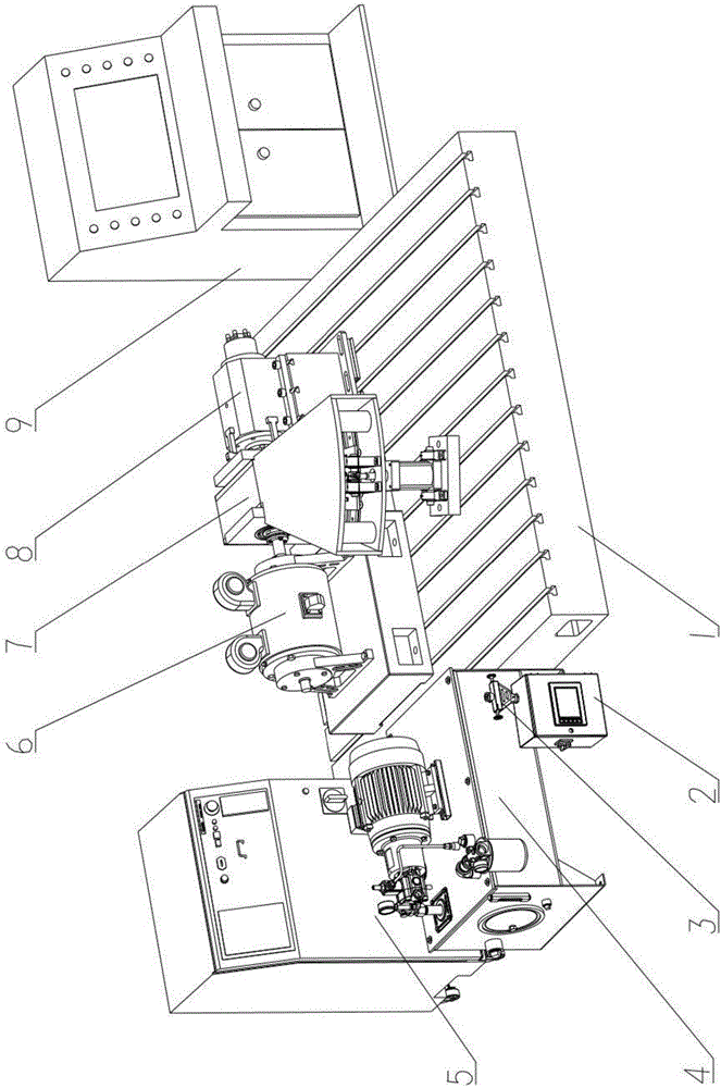
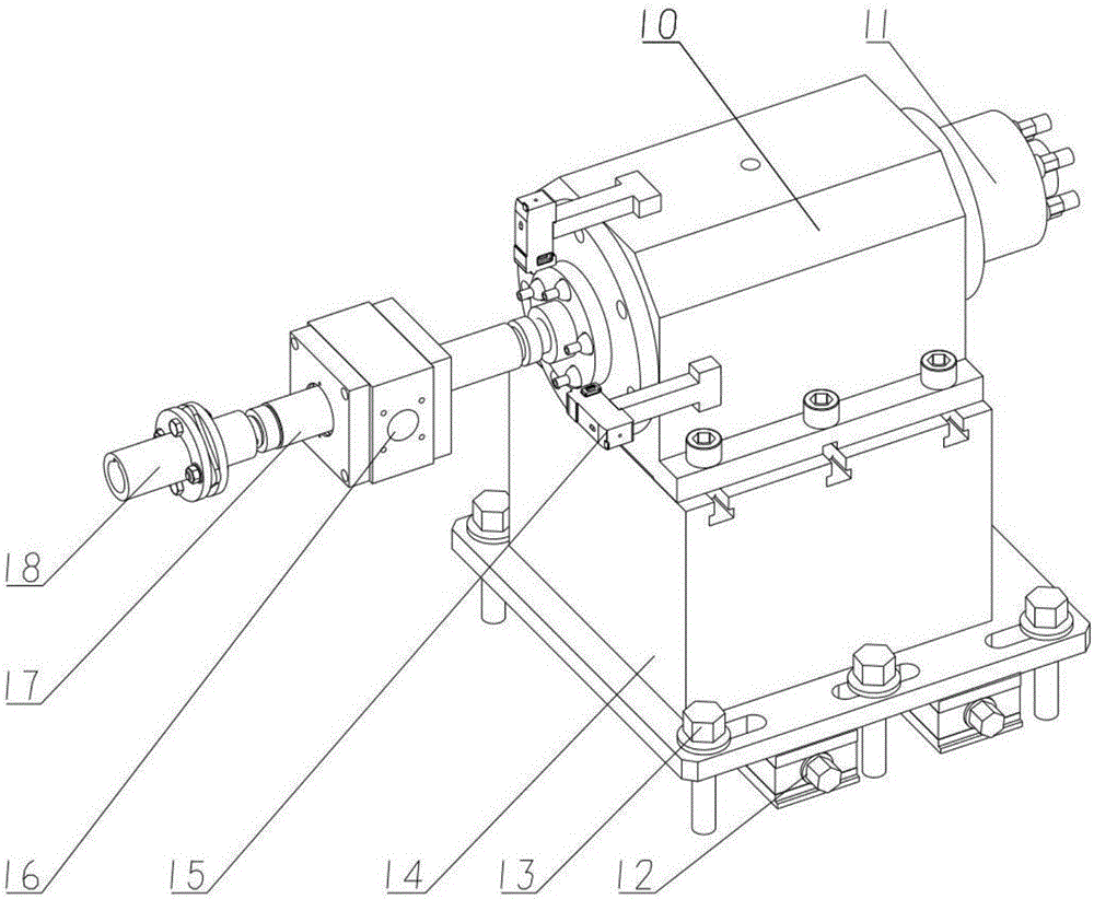
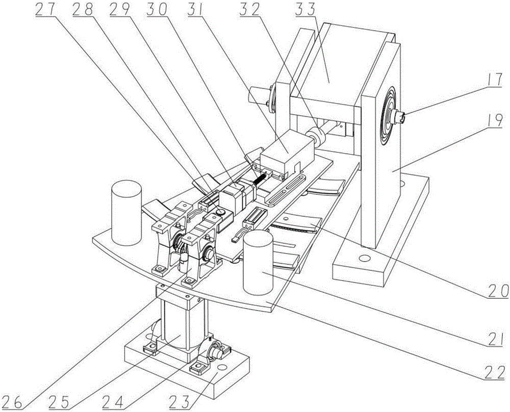
[0127] The spindle reliability test device described in the patent of the present invention is composed of five modules: spindle mounting table 8, cutting force automatic control device 7, cutting torque loading device, state monitoring equipment and auxiliary equipment.

[0128] refer to figure 1 , the composition structure of the spindle reliability test device includes a horizontal iron 1, an oil-air lubrication controller 2, a flow sensor 3, a hydraulic station 4, a cooling control cabinet 5, an electric dynamometer 6, an automatic cutting force control device 7, and a spindle installation Taiwan 8, industrial computer 9. Wherein the electric dynamometer 6, the cutting force automatic control device 7, and the main sh...


PUM


Abstract

The invention discloses and relates to a cutting force automatic control main shaft reliability test device and a test method, and belongs to the technical field of mechanical test equipment and method. The problems that in the prior art, the real work conditions of a main shaft cannot be accurately and dynamically simulated; the control mode is complicated; the equipment manufacturing cost is high are solved. The main shaft reliability test device consists of a main shaft installing table, a cutting force automatic control device, a cutting torque loading device, state monitoring equipment and auxiliary equipment, wherein the cutting force automatic control device consists of a cutting force magnitude loading mechanism, a cutting force direction regulating mechanism, an electromagnetic locking mechanism and a loading device support frame. The test method of the main shaft reliability test device comprises the following steps: 1, obtaining and processing the load and state parameters; 2, performing detection and debugging on the cutting force automatic control main shaft reliability test device before the work; 3, the cutting force automatic control main shaft reliability test device simulates the work condition loading experiments.

Description

technical field [0001] The invention belongs to the technical field of mechanical test equipment and methods, and relates to a spindle reliability test device for simulating the working conditions of a machine tool spindle and a spindle reliability test method. Background technique [0002] Spindle is one of the key components of CNC machine tools, and its reliability level directly affects the reliability of the whole machine. Carrying out the reliability test on the spindle, discovering its weak links and making targeted improvements can greatly improve the reliability of the machine tool. Therefore, a large number of reliability tests for machine tool spindles have been carried out at home and abroad. However, in the process of reliability testing of machine tool spindles, there are very few test devices that can approximate real working conditions. In the design of the loading device, most of the test benches at home and abroad can only realize the dynamic control of t...

Claims


Application Information

Patent Timeline
Patent Type & Authority Applications(China)
IPC IPC(8): G01M13/02
CPCG01M13/028
Inventor 陈玮峥陈菲杨兆军陈超郭劲言李世拯李强
Owner JILIN UNIV
Learn More