
RFID antenna device

An antenna device and antenna technology, applied in the direction of antenna support/installation device, antenna, radiation unit cover, etc., can solve the problems of antenna heat dissipation, inconvenient installation and disassembly, unfavorable signal transmission and reception, etc., and achieve signal coverage , to achieve the effect of adjustment

Active Publication Date: 2020-04-17
重庆壹城桥慧科技有限公司
View PDF14 Cites 0 Cited by
  • Summary
  • Abstract
  • Description
  • Claims
  • Application Information

AI Technical Summary

Problems solved by technology

[0005] The object of the present invention is to provide a kind of RFID antenna device, in order to solve the problem that the existing RFID antenna proposed in the above background technology is usually only directly fixed to the installation surface when it is installed, it is easy to cause difficulty in heat dissipation of the antenna, and it is inconvenient to install and disassemble. And it is not conducive to the problem of signal transmission and reception

Method used


Image

  • RFID antenna device
  • RFID antenna device
  • RFID antenna device

Examples


Embodiment Construction

[0020] The following will clearly and completely describe the technical solutions in the embodiments of the present invention with reference to the accompanying drawings in the embodiments of the present invention. Obviously, the described embodiments are only some, not all, embodiments of the present invention. Based on the embodiments of the present invention, all other embodiments obtained by persons of ordinary skill in the art without creative efforts fall within the protection scope of the present invention.

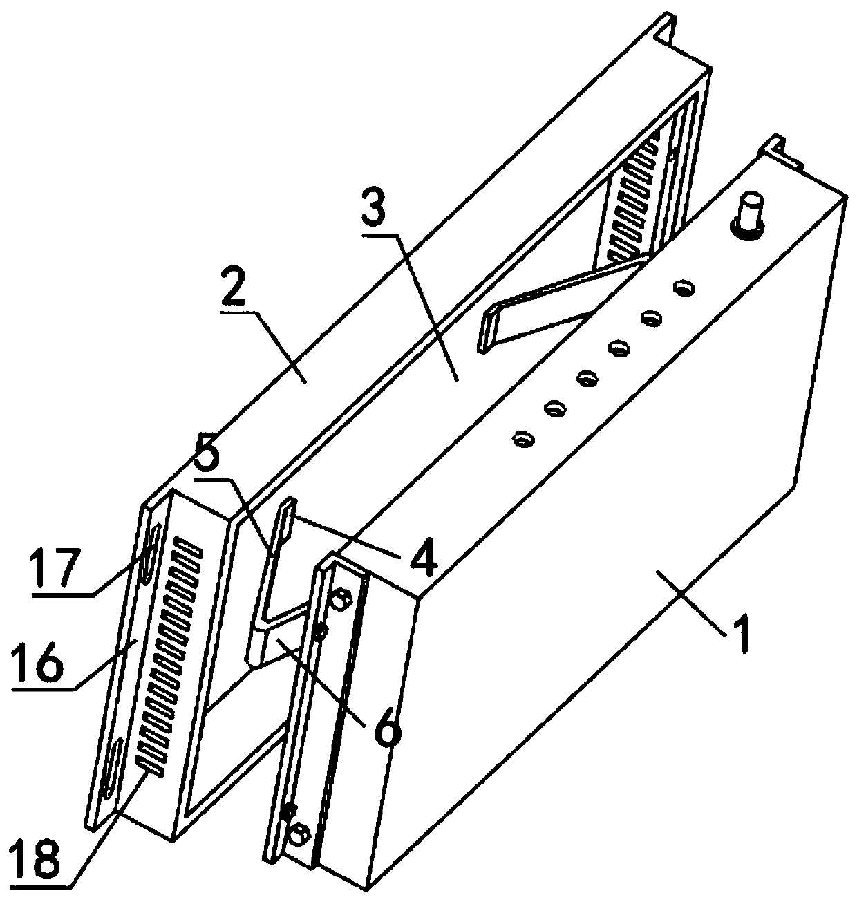
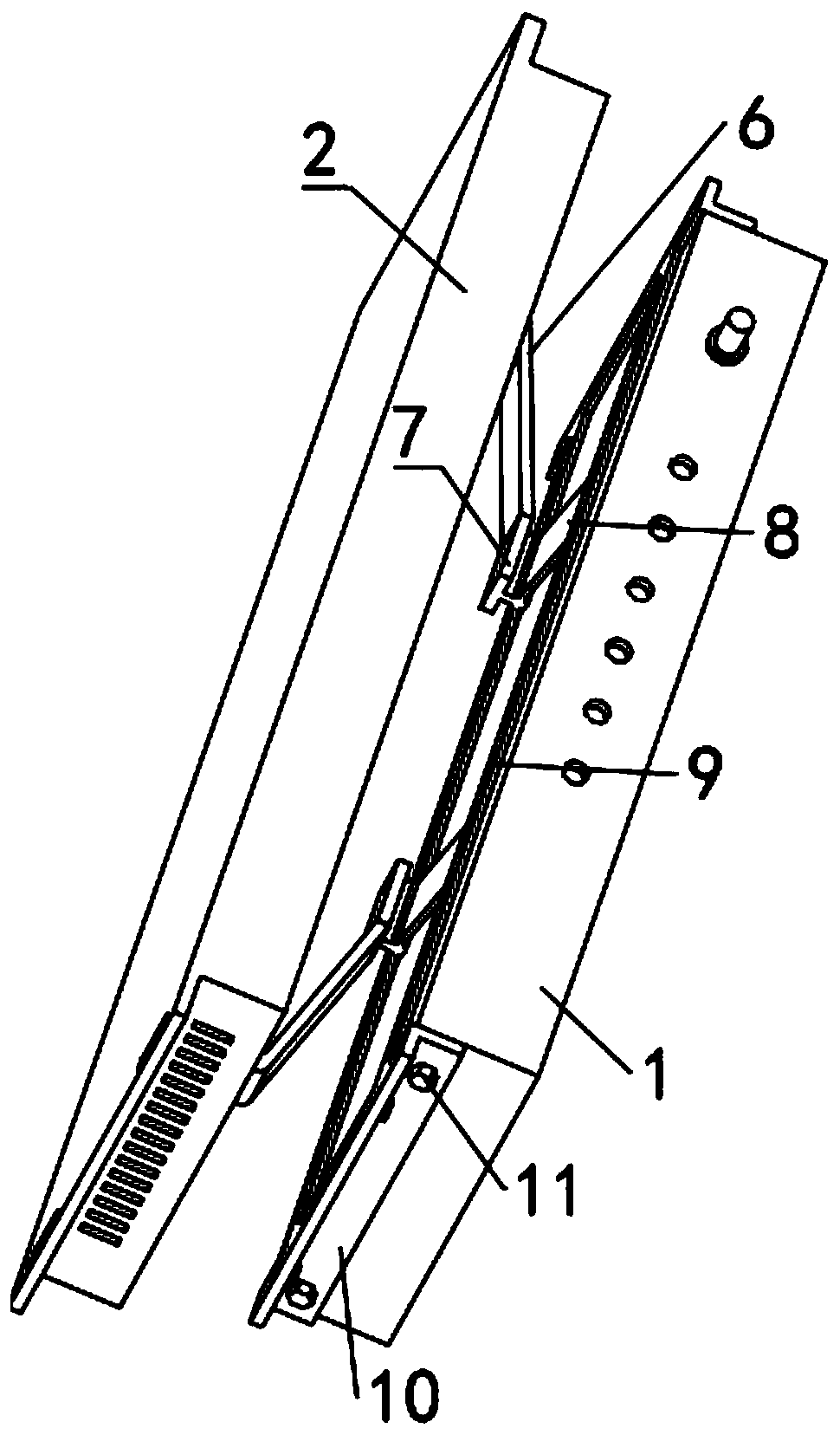
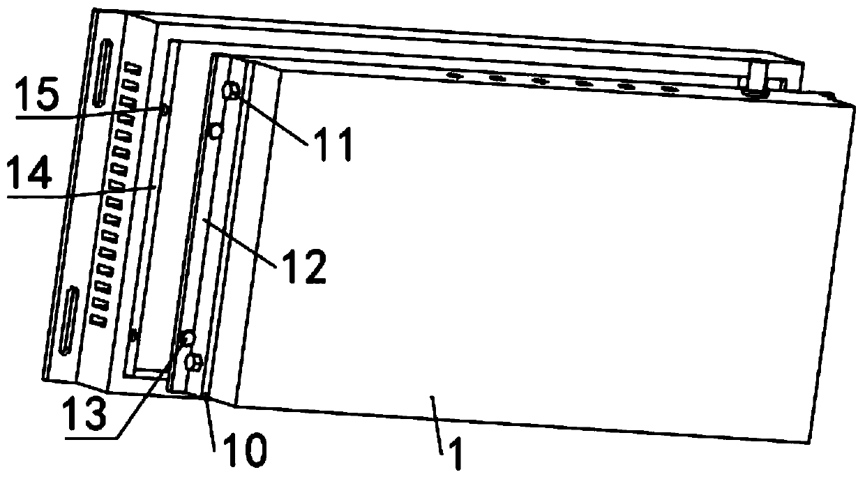
[0021] see Figure 1-3 The present invention provides a technical solution: an RFID antenna device, including an RFID antenna body 1 and an antenna storage box 2, the inner side wall of the antenna storage box 2 is provided with a storage slot 3 for the RFID antenna body 1, the Between the inner side wall of the storage groove 3 and one side of the RFID antenna body 1 is connected a stretch connection mechanism for the RFID antenna body 1 to be pulled out of the ou...


PUM


Abstract

The invention discloses an RFID antenna device in the technical field of antenna installation. The RFID antenna device comprises an RFID antenna body and an antenna storage box, and an inner side wallof the antenna storage box is provided with a storage groove for the RFID antenna body. A stretching connection mechanism used for pulling the RFID antenna body out of an outer side of the storage groove and an adjusting mechanism used for enabling the RFID antenna body to rotate up and down are connected between an inner side wall of the storage groove and one side of the RFID antenna body. According to the invention, an RFID antenna can be dismounted and mounted conveniently, and the signal coverage range of the RFID antenna can be adjusted by pulling out the RFID antenna and adjusting therotation angle when the RFID antenna works.

Description

technical field [0001] The invention relates to the technical field of antenna installation, in particular to an RFID antenna device. Background technique [0002] RFID system antennas are generally divided into two categories: electronic tag antenna design and reader antenna. The antenna design of RFID systems in different working frequency bands has its own characteristics. For LF and HF frequency bands, the system uses inductive coupling to work. The working energy required by the electronic tag is obtained by inductive coupling from the near-field radiation of the coupling coil of the reader. It is generally a passive system and the working distance is small, not greater than 1 rice. In fact, the near field of the reader does not involve the problem of electromagnetic wave propagation, and the antenna design is relatively simple. [0003] When the existing RFID antenna is installed, it is usually only directly fixed to the installation surface, which easily leads to d...

Claims


Application Information

Patent Timeline
Patent Type & Authority Applications(China)
IPC IPC(8): H01Q1/12H01Q1/42H01Q3/02
CPCH01Q1/12H01Q1/42H01Q3/02
Inventor 李程坡于桂芳
Owner 重庆壹城桥慧科技有限公司
Learn More