lmccd Imaging System with Low Interference Noise

An imaging system, low-interference technology, applied in parts of TV systems, image communication, color TV parts, etc., can solve problems such as mutual interference, avoid beat frequency interference, reduce electromagnetic emission, and avoid mutual interference Effect

Active Publication Date: 2021-06-01
CHANGCHUN INST OF OPTICS FINE MECHANICS & PHYSICS CHINESE ACAD OF SCI
View PDF6 Cites 0 Cited by
  • Summary
  • Abstract
  • Description
  • Claims
  • Application Information

AI Technical Summary

Problems solved by technology

[0003] In order to solve the problem of mutual interference in the existing LMCCD imaging because the linear array and the area array detectors are at the same focal plane position, the present invention provides an LMCCD imaging system with low interference noise

Method used


Image

  • lmccd Imaging System with Low Interference Noise
  • lmccd Imaging System with Low Interference Noise
  • lmccd Imaging System with Low Interference Noise

Examples


specific Embodiment approach 1

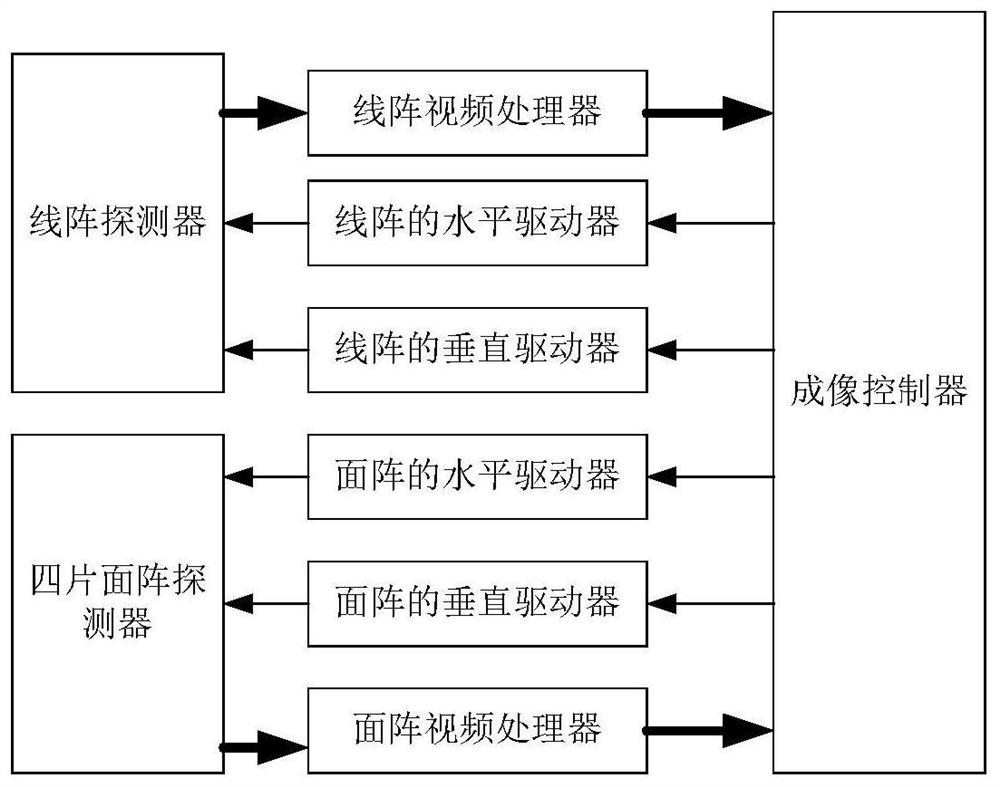
[0020] Specific implementation mode 1. Combination Figure 1 to Figure 5 Description of this embodiment, the LMCCD imaging system with low interference noise includes an imaging controller, a line array detector, a four-chip area array detector, a horizontal driver for the line array, a vertical driver for the line array, a horizontal driver for the area array, and a horizontal driver for the area array. Vertical driver, video processor of line array and video processor of area array; imaging controller generates timing signals required by line array and area array, driven by horizontal and vertical drivers respectively, and sent to line array and area array imaging detection device. The analog image data output by the line array and area array imaging detectors are sent to the imaging controller after video processing by the line array and area array video processors respectively.

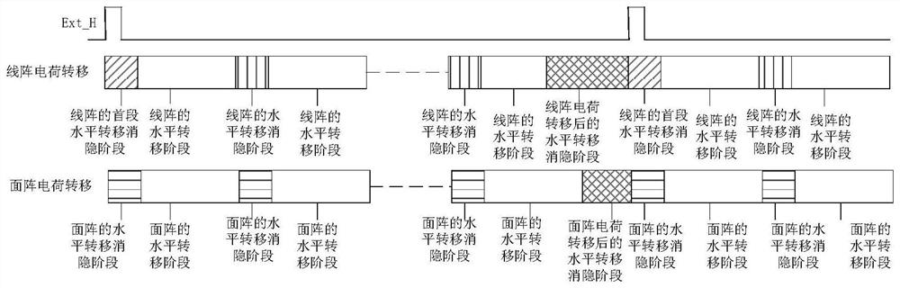
[0021] In this embodiment, the frame readout period t of the area array area_frame Contains ...


PUM


Abstract

The LMCCD imaging system with low interference noise relates to an LMCCD imaging system with low interference noise, which solves the problem of mutual interference in the existing LMCCD imaging because the linear array and the area array detectors are at the same focal plane position, and the imaging controller Generate the timing signals required by the line array and the area array, and send them to the line array detector and the area array imaging detector after passing through the horizontal driver of the line array, the vertical driver of the line array, the horizontal driver of the area array and the vertical driver of the area array respectively ; The analog image data output by the line array detector and the area array imaging detector are sent to the imaging controller after video processing by the line array video processor and the area array video processor respectively; the line array and the area array are controlled by the same source clock, Avoid beat frequency interference; reduce mutual return overlap by ground isolation and single-point grounding; reduce electromagnetic emission by reducing the rising and falling edge time of the drive circuit; by ensuring the same blanking period of the linear array and the area array, Avoid transitions in the drive signal that interfere with the signal being transferred.

Description

technical field [0001] The invention relates to an LMCCD imaging system with low interference noise, in particular to an LMCCD imaging system with low interference noise aimed at aerospace applications. Background technique [0002] The principle of the LMCCD (Line-Matrix Array CCD) camera is based on the three-line array detector camera, adding four small area arrays at the four corners of the line-matrix array detector to form a line-matrix array mixed configuration camera. In the EFP (equivalent frame photo) method of the LMCCD image, the selection of the image point is completed on the front-view image, and the image matching method is applied to obtain the same-name point of the area detector image, and calculate its real frame coordinates at the EFP moment , and at the EFP moment, the real image plane coordinates of the connecting points are added as observation values, so that many triangular lock models in the route are better integrated, and the adjustment height ac...

Claims


Application Information

Patent Timeline
Patent Type & Authority Patents(China)
IPC IPC(8): H04N5/217H04N5/372
CPCH04N23/81H04N25/71
Inventor 余达刘金国周怀得郭疆张艳鹏王浩张琨
Owner CHANGCHUN INST OF OPTICS FINE MECHANICS & PHYSICS CHINESE ACAD OF SCI
Why Eureka
Try Eureka