Controller for adjusting industrial camera lens and control method
A technology of industrial cameras and control methods, which is applied to TVs, color TV parts, electrical components, etc., can solve problems such as time-consuming, low accuracy, and unattended unattended, so as to save focusing time and improve shooting The effect of precision
- Summary
- Abstract
- Description
- Claims
- Application Information
AI Technical Summary
Problems solved by technology
Method used
Image

Examples
Embodiment 1
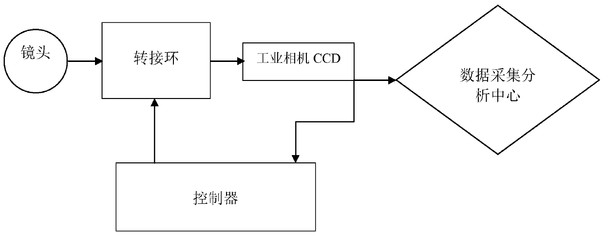
[0042] A controller for industrial camera lens adjustment, as attached figure 1 As shown, one end of the controller is connected to a CCD image sensor for receiving images, and the other end is connected to an adapter ring for controlling the lens.
[0043] The controller includes a memory, a mainboard flash memory, a USB interface, an image access module, an image preprocessing analysis module and a lens adapter ring control module.
[0044]The memory is 512MB DDR3 RAM, and the mainboard flash memory is 4GB, 8-bit mainboard flash memory (4GB 8-biteMMC on-board flash).
[0045] The USB interface is used to connect the adapter ring.
[0046] Further, the controller also includes a UART serial port interface, and the UART serial port interface is used for connecting to an adapter ring.
[0047] Further, the controller also includes an Ethernet interface, and the Ethernet interface is 1000M, which is used for connecting the adapter ring.
[0048] Further, the controller adopts...
Embodiment 2
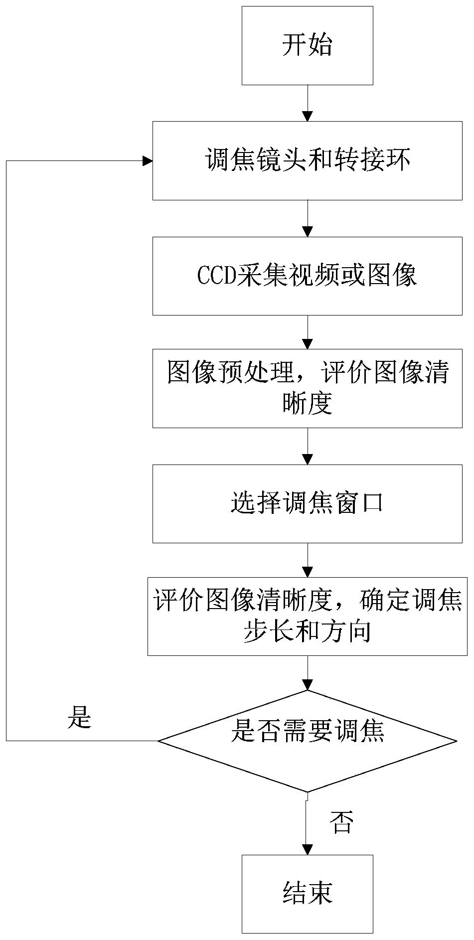
[0051] Based on the above-mentioned embodiment 1, a control method of a controller for adjusting an industrial camera lens, as attached figure 2 shown, including the following steps:
[0052] 101. The CCD image sensor transmits the collected video signal to the controller.
[0053] Among them, the CCD image sensor transmits the collected video signal in two ways, one way is transmitted to the data acquisition and analysis center for storage and processing, and the other way is transmitted to the auto-focus controller.
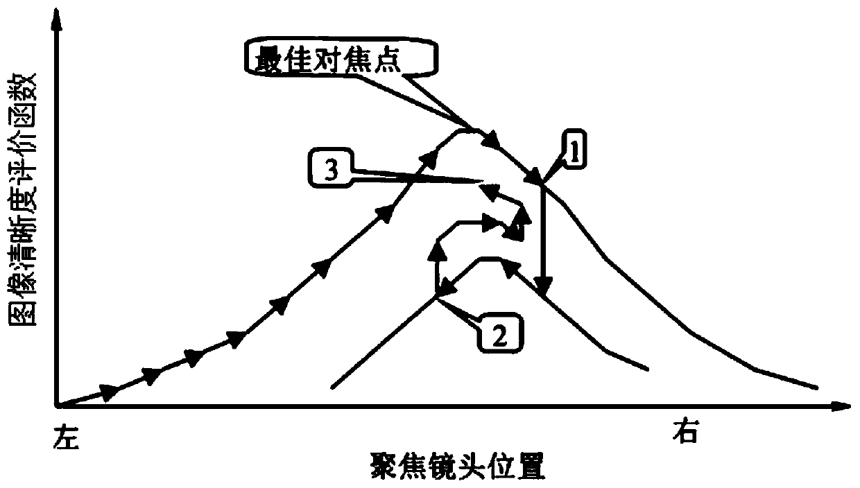
[0054] 102. The controller processes each frame of image in real time, evaluates the clarity of the image, and judges whether the image of the object is clear and whether the focus is accurate.
[0055] Among them, the evaluation of image sharpness is based on the characteristics of the measured object, using an automatic focusing evaluation function based on the multi-directional maximum gradient threshold, that is, the image sharpness evaluation function, w...
PUM
 Abstract
Description
Claims
Application Information
 - Generate Ideas
- Intellectual Property
- Life Sciences
- Materials
- Tech Scout
- Unparalleled Data Quality
- Higher Quality Content
- 60% Fewer Hallucinations
Browse by: Latest US Patents, China's latest patents, Technical Efficacy Thesaurus, Application Domain, Technology Topic, Popular Technical Reports.
© 2025 PatSnap. All rights reserved.Legal|Privacy policy|Modern Slavery Act Transparency Statement|Sitemap|About US| Contact US: help@patsnap.com