
Electronic equipment

A technology for electronic equipment and shells, which is applied in the field of electronic equipment, can solve problems such as large impact and damage to electronic equipment, and achieve the effects of alleviating impact, avoiding large inertia, and stabilizing movement

Inactive Publication Date: 2020-04-17
VIVO MOBILE COMM HANGZHOU CO LTD
View PDF9 Cites 1 Cited by
  • Summary
  • Abstract
  • Description
  • Claims
  • Application Information

AI Technical Summary

Problems solved by technology

[0004] The invention discloses an electronic device to solve the problem that the electronic device is easily damaged due to the relatively large impact of the moving module of the current electronic device during the pop-up process.

Method used


Image

  • Electronic equipment
  • Electronic equipment
  • Electronic equipment

Examples


Embodiment Construction

[0033] In order to make the purpose, technical solution and advantages of the present invention clearer, the technical solution of the present invention will be clearly and completely described below in conjunction with specific embodiments of the present invention and corresponding drawings. Apparently, the described embodiments are only some of the embodiments of the present invention, but not all of them. Based on the embodiments of the present invention, all other embodiments obtained by persons of ordinary skill in the art without making creative efforts belong to the protection scope of the present invention.

[0034] The technical solutions disclosed by various embodiments of the present invention will be described in detail below in conjunction with the accompanying drawings.

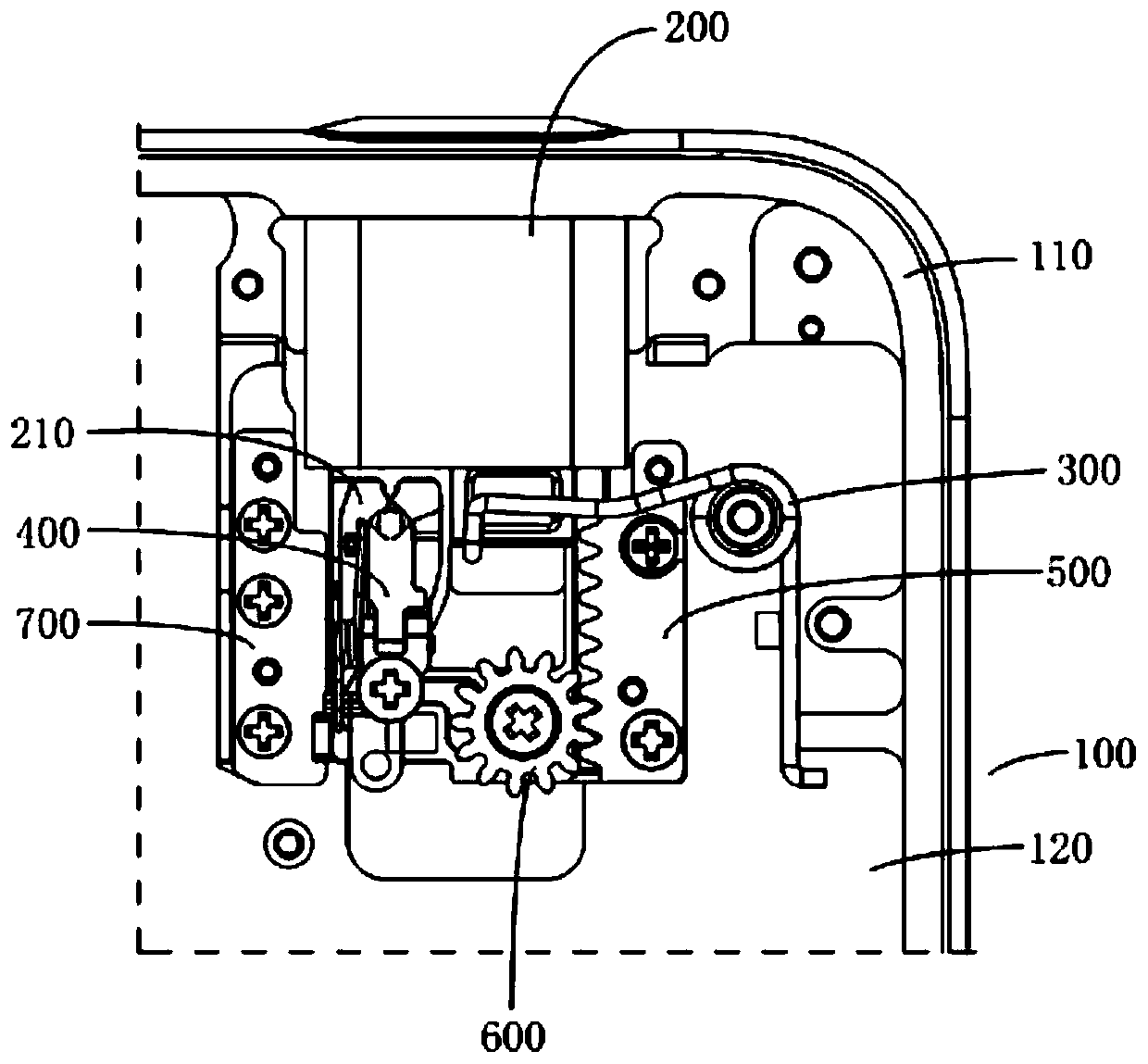
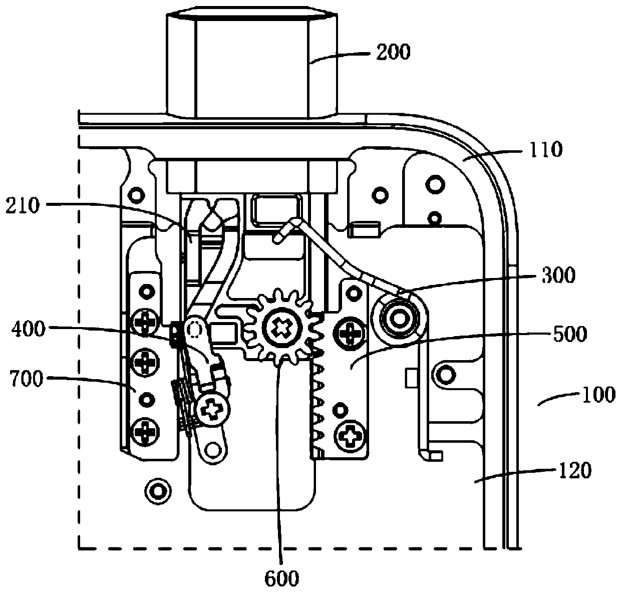
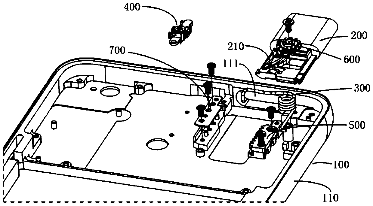
[0035] Please refer to Figure 1 to Figure 17 , the embodiment of the present invention discloses an electronic device, and the disclosed electronic device includes a casing 100 , a motion modu...


PUM


Abstract

The invention discloses electronic equipment comprising a shell, a motion module and a first elastic driving piece. The shell is provided with an opening, and the shell is provided with an inner cavity communicating with the opening; the motion module is arranged on the shell and can retract into the inner cavity through the opening or at least partially extend out of the shell; the first elasticdriving piece is arranged in the shell and can drive at least part of the motion module to extend out of the shell through the opening; one of the shell and the moving module is provided with a rack,and the rack extends in the moving direction of the moving module; one of the shell and the motion module is provided with a rack, and the rack extends in the moving direction of the motion module; the other one of the shell and the motion module is provided with a rotatable rotating piece, the rotating piece is provided with gear teeth, and the gear teeth are meshed with the rack. According to the scheme, the problem that the electronic equipment is easily damaged due to large impact in the popup process of the motion module of the existing electronic equipment can be solved.

Description

technical field [0001] The present invention relates to the technical field of communication equipment, in particular to an electronic equipment. Background technique [0002] In order to increase the screen-to-body ratio of electronic devices, more and more electronic devices are equipped with lifting motion modules, such as lifting cameras. The lifting movement of the motion module is driven by the drive mechanism. [0003] In order to reduce energy consumption, current electronic equipment is usually equipped with a manually-controlled pop-up mechanism, and the user can manually control the movement module to lift up and down during use. However, in actual use, if you press the motion module manually, the motion module will pop out of the device casing. During this process, the motion module will generate a large inertia during the extension process, which will cause a large impact on the casing, and eventually cause damage to the electronic device. Contents of the in...

Claims


Application Information

Patent Timeline
Patent Type & Authority Applications(China)
IPC IPC(8): H05K7/14H05K5/02H04M1/02
CPCH04M1/026H04M1/0264H05K5/0217H05K7/14
Inventor 张立国冯安明
Owner VIVO MOBILE COMM HANGZHOU CO LTD
Learn More