Charged particle beam device
A technology of charged particle beam and electron beam, applied in circuits, discharge tubes, electrical components, etc., can solve problems such as influence and leakage, and achieve the effect of reducing residual magnetic field
- Summary
- Abstract
- Description
- Claims
- Application Information
AI Technical Summary
Problems solved by technology
Method used
Image
Examples
Embodiment approach 1
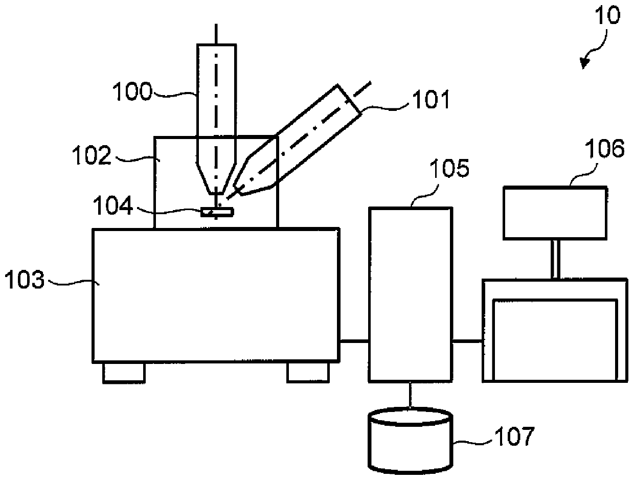
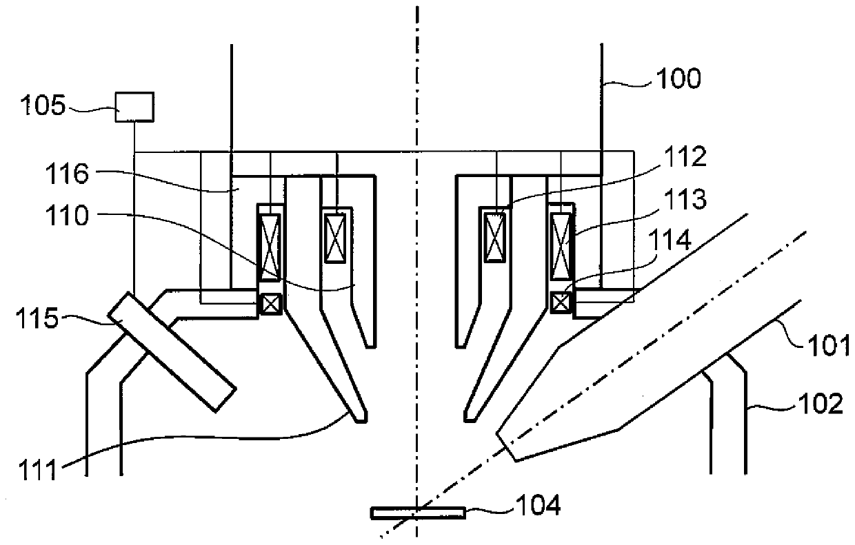
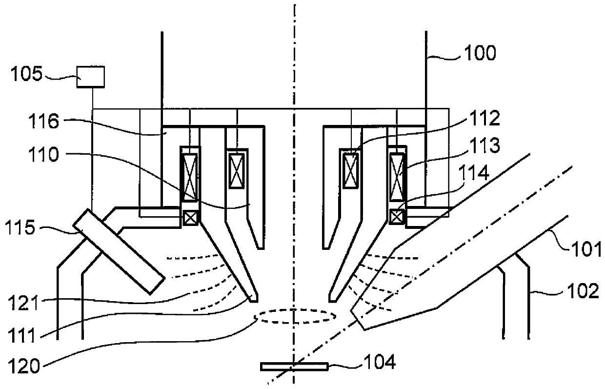
[0025] figure 1 It is a configuration diagram of a charged particle beam device 10 according to Embodiment 1 of the present invention. It is a diagram showing the structure of the FIB-SEM device. The charged particle beam device 10 is configured as a FIB-SEM device. The charged particle beam device 10 includes an SEM lens barrel 100, a FIB lens barrel 101, a sample chamber 102, a FIB-SEM gantry 103, a controller 105, a monitor 106, and a storage device 107. The FIB lens barrel 101 irradiates the sample 104 with FIB in order to process or observe the sample 104. The SEM barrel 100 irradiates the sample 104 with an electron beam in order to observe and analyze the sample 104 with high resolution. The sample chamber 102 is a space where the sample 104 is installed, and includes the above-mentioned lens barrels. The FIB-SEM stand 103 mounts the sample chamber 102. The controller 105 obtains the SEM observation image of the sample 104 by controlling the charged particle beam dev...
Embodiment approach 2
[0068] Figure 7 It is a configuration diagram of the objective lens of the SEM barrel 100 included in the charged particle beam device 10 according to Embodiment 2 of the present invention. The charged particle beam device 10 according to the second embodiment is different from the first embodiment in that the third coil 114 is not provided. The other structure is the same as the first embodiment. In the second embodiment, both the first mode and the second mode are implemented using the second coil 113. Since the third coil 114 is not used, the value of the current flowing through the second coil 113 in each mode may be different from that of the first embodiment, but the operation sequence is the same as that of the first embodiment.
[0069] Since the second coil 113 has both the task of forming a magnetic lens and the task of suppressing the residual magnetic field, it has the largest number of turns among the three coils. That is, the number of turns of the second coil≥th...
Embodiment approach 3
[0071] Figure 8 It is a configuration diagram of the objective lens of the SEM barrel 100 included in the charged particle beam device 10 according to Embodiment 3 of the present invention. Either or both of the first coil 112 and the second coil 113 can be divided into a plurality of coils. in Figure 8 An example in which both the first coil 112 and the second coil 113 are divided into two coils is shown in FIG.
[0072] In order to stabilize the magnetic field generated from the pole piece, it is important to suppress the temperature change of the pole piece. In order to suppress the temperature change of the pole piece, it is only necessary to keep the power consumption of the coil constant. In order to adjust the magnetic field while keeping the power consumption of the coil constant, it is only necessary to change the direction of the current while keeping the magnitude of the current flowing through the coil constant. For example, in Figure 8 In the coils 112A and 1...
PUM
 Abstract
Description
Claims
Application Information
 - R&D
- Intellectual Property
- Life Sciences
- Materials
- Tech Scout
- Unparalleled Data Quality
- Higher Quality Content
- 60% Fewer Hallucinations
Browse by: Latest US Patents, China's latest patents, Technical Efficacy Thesaurus, Application Domain, Technology Topic, Popular Technical Reports.
© 2025 PatSnap. All rights reserved.Legal|Privacy policy|Modern Slavery Act Transparency Statement|Sitemap|About US| Contact US: help@patsnap.com


