
Locking and charging integrated charging pile

A charging pile and charging box technology, applied in charging stations, electric vehicle charging technology, electric vehicles, etc., can solve problems such as difficulty in driving, and achieve the effects of preventing theft, facilitating daily travel, and strong functionality

Inactive Publication Date: 2020-04-21
湖北德普电气股份有限公司
View PDF9 Cites 0 Cited by
  • Summary
  • Abstract
  • Description
  • Claims
  • Application Information

AI Technical Summary

Problems solved by technology

[0003] The purpose of the present invention is to solve the disadvantages in the prior art that automatic vehicles are difficult to push when there is no electricity, and propose a charging pile with integrated locking and charging

Method used


Image

  • Locking and charging integrated charging pile
  • Locking and charging integrated charging pile
  • Locking and charging integrated charging pile

Examples


Embodiment 1

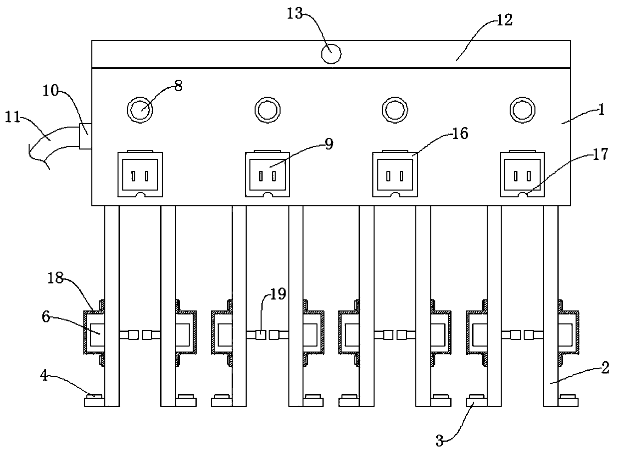
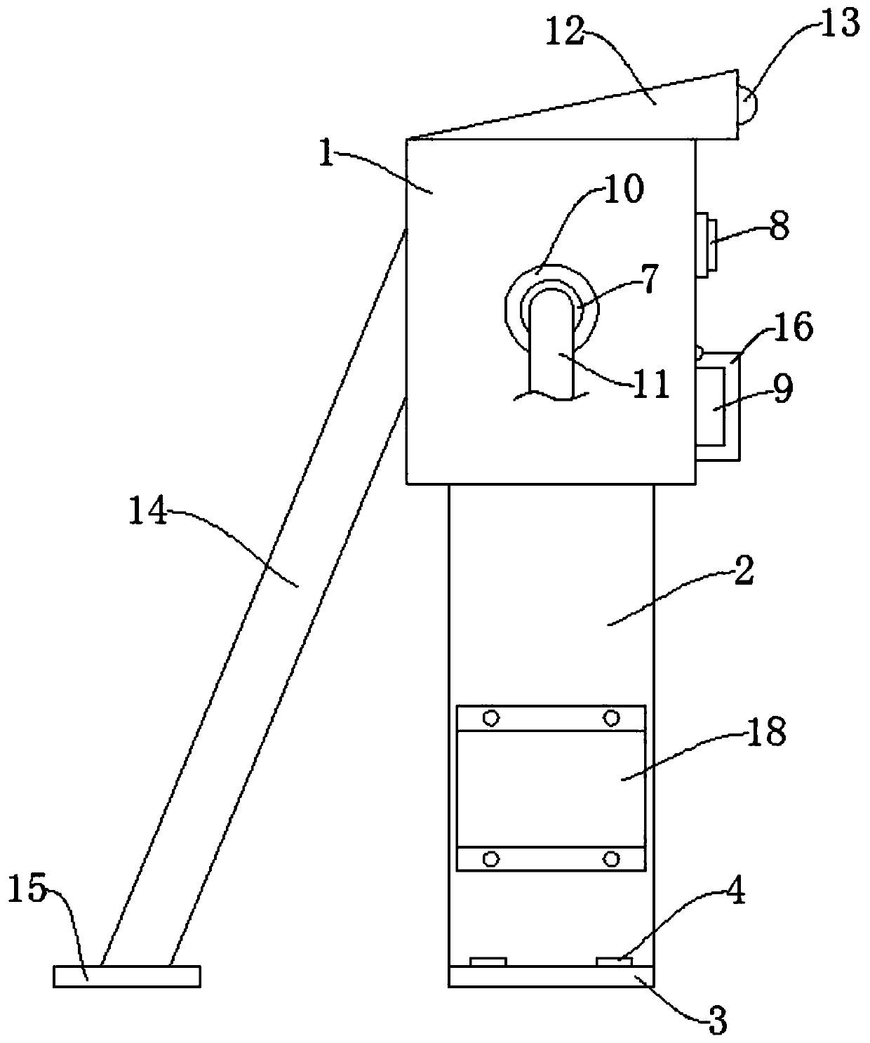
[0020] refer to Figure 1-4 , a charging pile with locking and charging integration, comprising a charging box 1, the bottom of the charging box 1 is fixedly welded with a supporting vertical plate 2, the bottom end of the supporting vertical plate 2 is fixedly welded with a connecting piece 3, and the connecting piece 3 is provided with a fixed Bolt 4, the fixing bolt 4 passes through the connecting piece 3 and is connected to the ground, under the action of the fixing bolt 4, the connecting piece 3 can be fixed on the ground, so that the positions of the support riser 2 and the charging box 1 are fixed.

[0021] The support risers 2 form a group of two, and each set of support risers 2 is provided with a locking mechanism, the locking mechanism includes a hole 5 opened on the support riser 2, and the hole 5 is close to the vertical side wall of the support riser 2 , the support vertical plate 2 is equipped with an electric telescopic rod 6, the output end of the electric tel...

Embodiment 2

[0024] refer to Figure 1-2 , as another preferred embodiment of the present invention, the difference from Embodiment 1 is that a slope 12 is provided on the top of the charging box 1, and a monitoring camera 13 is installed on the slope 12. The setting of the slope 12 is to increase the water turning capacity , in rainy and snowy weather, the rainwater and snow on the slope 12 can slide down from the slope 12, thereby avoiding the accumulation of water on the charging box 1, causing the top of the charging box 1 to rust, and the installation of the monitoring camera 13 can be done to a greater extent superior.

Embodiment 3

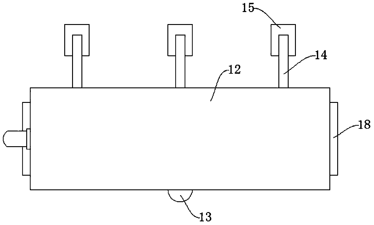
[0026] refer to Figure 2-3 , as another preferred embodiment of the present invention, the difference from Embodiment 1 is that a reinforcing mechanism is provided on the back side of the charging box 1, and the reinforcing mechanism includes a reinforcing slanting bar 14 fixedly welded on the back side of the charging box 1, and the reinforcing slanting bar 14 The side away from the charging box 1 is fixedly welded with a support plate 15, and the setting of the reinforcing slant bar 14 and the support plate 15 can effectively strengthen the stability of the charging pile, so that the charging pile can be firmly fixed on the ground even in bad weather superior.


PUM


Abstract

The invention relates to the technical field of public facilities. The invention relates to a charging pile, in particular to a locking and charging integrated charging pile which comprises a chargingbox, supporting vertical plate are fixedly welded to the bottom of the charging box; connecting pieces are fixedly welded at the bottom ends of the supporting vertical plates; fixing bolts are arranged on the connecting pieces and penetrate through the connecting pieces to be connected with the ground, every two supporting vertical plates form a set, a locking mechanism is arranged in each set ofsupporting vertical plates, each locking mechanism comprises holes formed in the corresponding supporting vertical plates, the holes are close to the vertical side walls of the supporting vertical plates, and electric telescopic rods are installed on the supporting vertical plates. By installing the temporary charging piles on the roadsides, daily travel of people can be facilitated, when electric vehicles run out of power, temporary charging can be conducted, daily travel of people is facilitated, the charging pile adopts the locking and charging integrated design, when the electric vehiclesare charged, wheels can be locked, stealing is prevented, and the charging pile is high in functionality and suitable for popularization.

Description

technical field [0001] The invention relates to the technical field of public facilities, in particular to a charging pile with integrated locking and charging. Background technique [0002] With the development of science and technology, people's lives have undergone earth-shaking changes. Electric vehicles have now generally replaced bicycles as people's daily transportation. However, the driving distance of electric vehicles is limited, and the weight of the body is heavy. , It is difficult for people to push. In order to make people's daily life more convenient, we have designed a charging pile that can be charged temporarily. This charging pile can realize the function of temporarily locking the car while charging. Contents of the invention [0003] The purpose of the present invention is to solve the disadvantages in the prior art that the automatic vehicle is difficult to push when there is no electricity, and propose a charging pile with integrated locking and char...

Claims


Application Information

Patent Timeline
IPC IPC(8): B60L53/31
CPCB60L53/31B60L2200/46Y02T10/70Y02T10/7072Y02T90/12
Inventor 刘士杰程京京胡伟锋
Owner 湖北德普电气股份有限公司
Learn More