
Array resistivity focusing system and focusing method in laboratory

A technology focusing on the system and resistivity, applied in earthwork drilling, measurement, borehole/well components, etc., can solve problems affecting the measurement accuracy of apparent resistivity, solve the problem of small signal measurement accuracy, and solve the problem of inaccurate measurement accuracy problem, the effect of meeting the requirements of detection depth and resolution

Pending Publication Date: 2020-04-21
中国电波传播研究所
View PDF0 Cites 2 Cited by
  • Summary
  • Abstract
  • Description
  • Claims
  • Application Information

AI Technical Summary

Problems solved by technology

[0003] The technical problem to be solved by the present invention is to provide an array resistivity focusing system and focusing method in the laboratory, to at least solve the problem of affecting the measurement accuracy of apparent resistivity when multiple hardware focusing systems are cascaded in the related art

Method used


Image

  • Array resistivity focusing system and focusing method in laboratory
  • Array resistivity focusing system and focusing method in laboratory
  • Array resistivity focusing system and focusing method in laboratory

Examples


Embodiment 1

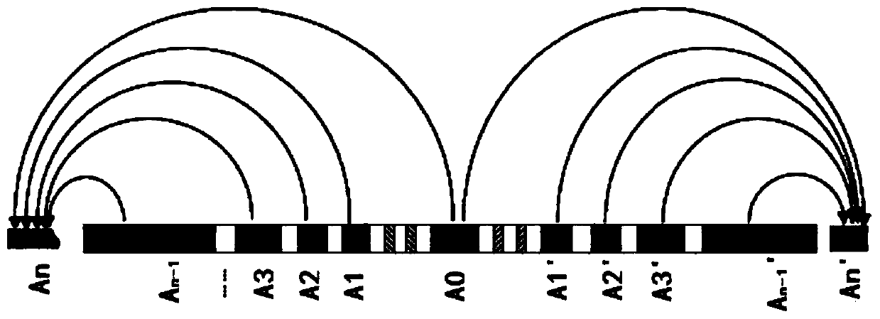
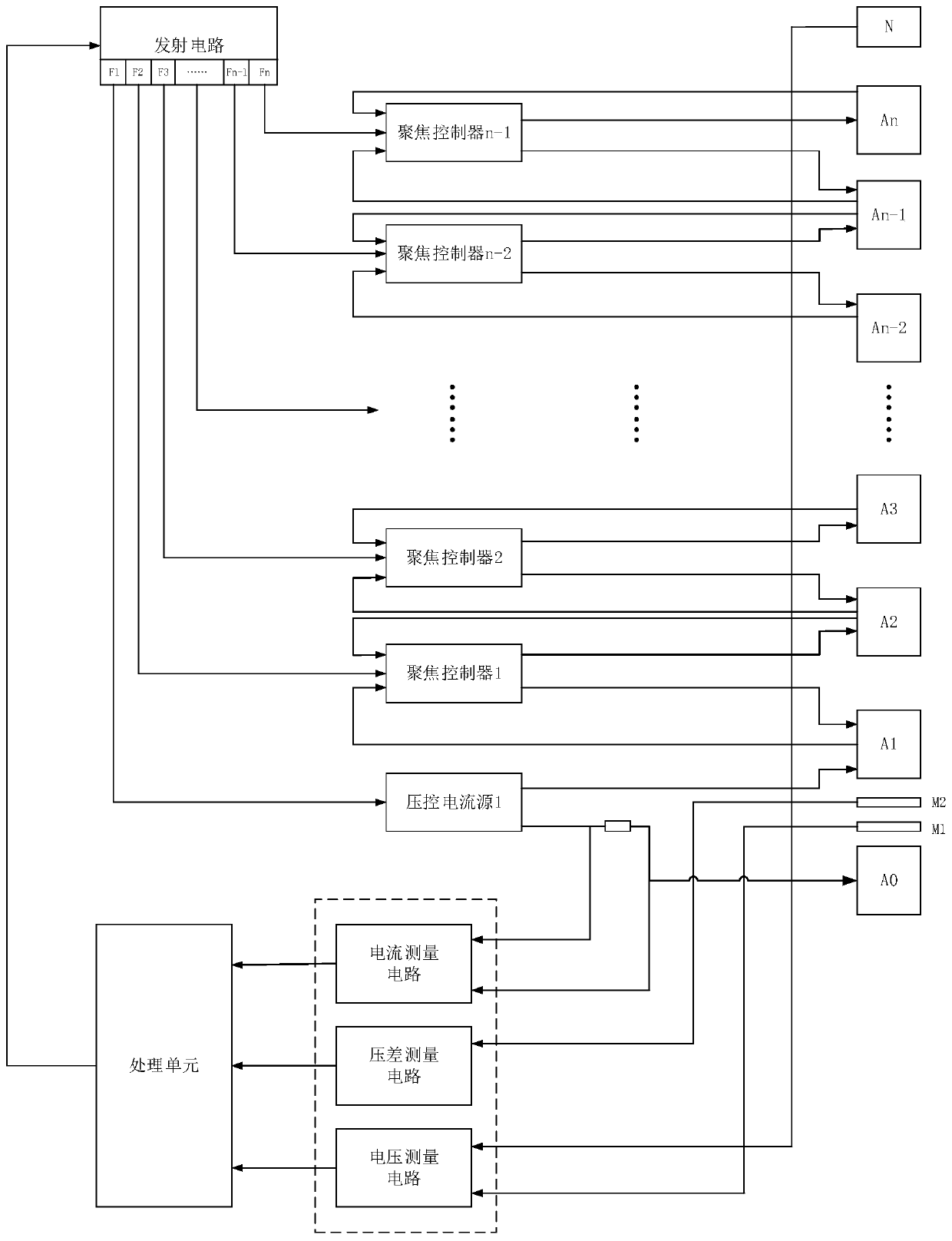
[0018] Example 1, such as Figure 1-3 As shown, this embodiment discloses an array resistivity focusing system in a laboratory, which includes a voltage-controlled current source, a focusing controller, a main emitting electrode A0, shielding electrodes A1 to An-1, and A1' to An symmetrical to it. -1', return electrodes An and An', and two pairs of supervision electrodes (M1, M2 and M1', M2') between A0 and A1, and between A0 and A1'. The symmetrical electrodes are connected in pairs, so only one of the symmetrical electrodes is considered in the following description. This type of array resistivity electrode requires n power supply modes.

[0019] This embodiment also discloses a method for focusing array resistivity in a laboratory. A voltage-controlled current source is connected to the main electrode A0 and the shield electrode A1, using mode 1 to emit current, and the current I output by the main electrode A0 is detected by a current detector. 0 .

[0020] The focus controll...

Embodiment 2

[0029] Example 2: In this example, a voltage-controlled current source is used to replace the focus controller n-1 in example 1, which can more conveniently perform deeper exploration, such as Figure 4 Shown.

[0030] Voltage controlled current source connected to shield electrode A n-1 With return electrode A n , Using mode n emission current. The rest of the structure and working mode are the same as in Example 1, and will not be repeated.

[0031] The voltage-controlled current source 1 is connected to the main electrode A0 and the shield electrode A1, adopts mode 1 to emit current, and detects the current I output by the main electrode A0 through a current detector 0 .

[0032] The monitoring electrode is used to monitor the potential difference V under n transmission modes at any time M1M2(n) .

[0033] The focusing system is also provided with a reference electrode N that provides a potential reference for the potential on the shield electrode. According to the reference electr...


PUM


Abstract

The invention discloses an array resistivity focusing system and method in a laboratory. The system involves a voltage-controlled current source, a focusing controller, a main transmitting electrode A<0>, shielding electrodes A<1>-A<n-1>, shielding electrodes A<1>'-A<n-1>' which are symmetrical to the shielding electrodes A<1>-A<n-1>, backflow electrodes A<n> and A<n>', two pairs of supervision electrodes M<1>, M<2> and M<1>', M<2>' arranged between A<0> and A<1> and between A<0> and A<1>'. According to the array resistivity focusing system and focusing method in the laboratory, a digital focusing synthesis method is adopted between the main transmitting electrode and the shielding electrodes, hardware focusing cascading is adopted between the shielding electrodes and the shielding electrodes, and the digital focusing and the hardware focusing are combined, so that the problem of inaccurate measurement precision caused by residual potential of pure hardware focusing is well solved. Meanwhile, the problem of small-signal measurement precision of a pure digital circuit is solved, and the complexity of pure digital focusing calculation is greatly simplified. The focusing controller can carry out corresponding addition or deletion according to the increase or decrease of the array electrodes so as to meet the requirements of the laboratory on detection depth and resolution, and isflexible and changeable; and the V-I design of the backflow electrodes can realize deeper-stratum detection according to experiment requirements.

Description

Technical field [0001] The invention belongs to the field of resistivity logging, and particularly relates to an array resistivity focusing system and focusing method in a laboratory in this field. Background technique [0002] In logging measurement and evaluation, the resistivity curve has become the three indispensable logging curves (deep, medium, and shallow) among the nine lines of conventional logging. With the demand for thin and thin interbed development in exploration wells, Gradually increase the resistivity measurement of the array. This arrayed measurement method requires multiple focusing systems to work simultaneously to present multiple radial measurement curves with different depths. Under normal circumstances, when focusing the emission current, the hardware focusing method is usually used to make the transmitting electrode and the shield electrode meet the focusing conditions, but there must be residual potential in the hardware focusing method, which reduces ...

Claims


Application Information

Patent Timeline
Patent Type & Authority Applications(China)
IPC IPC(8): E21B49/00E21B47/00
CPCE21B47/00E21B49/00
Inventor 夏济根李智强焦利明
Owner 中国电波传播研究所
Learn More