
Two-dimensional coordinate system rotation compensation measurement method and device

A technology of rotation compensation and coordinate system, which is used in semiconductor/solid-state device testing/measurement, electrical components, circuits, etc., and can solve problems such as inaccurate precision, affecting product chip placement accuracy, and inaccurate measurement of mechanical coordinate systems.

Active Publication Date: 2020-01-14
武汉东飞凌科技有限公司
View PDF10 Cites 0 Cited by
  • Summary
  • Abstract
  • Description
  • Claims
  • Application Information

AI Technical Summary

Problems solved by technology

[0003] At present, the measurement of TO package die-bonding placement has always been measured with the mechanical coordinate system of the measuring equipment as the reference coordinate system; for example, in the packaging process of TO-CAN 46 products, there are 2PIN, 3PIN, 4PIN... For tube sockets with various pin positions such as 8PIN, due to the mismatch of the measurement fixture and the rotation of the tube socket during the packaging process, the accuracy of normal measurement is inaccurate, especially in high-speed products (Note: high-speed products have a negative impact on the photosensitive surface of the chip. Eccentric mounting is required to meet the requirements of the return loss of the product during use and to ensure normal signal transmission)
[0004] The mechanical coordinate system of the product cannot be measured accurately due to the slight rotation of the TO tube holder, which will seriously affect the chip placement accuracy of the product, and eventually cause the product performance to fail to meet the requirements

Method used


Image

  • Two-dimensional coordinate system rotation compensation measurement method and device
  • Two-dimensional coordinate system rotation compensation measurement method and device
  • Two-dimensional coordinate system rotation compensation measurement method and device

Examples


Embodiment Construction

[0023] In order to make the purpose, technical solutions and advantages of the embodiments of the present invention clearer, the technical solutions in the embodiments of the present invention will be clearly and completely described below in conjunction with the drawings in the embodiments of the present invention. Obviously, the described embodiments It is a part of embodiments of the present invention, but not all embodiments. Based on the embodiments of the present invention, all other embodiments obtained by persons of ordinary skill in the art without creative efforts fall within the protection scope of the present invention.

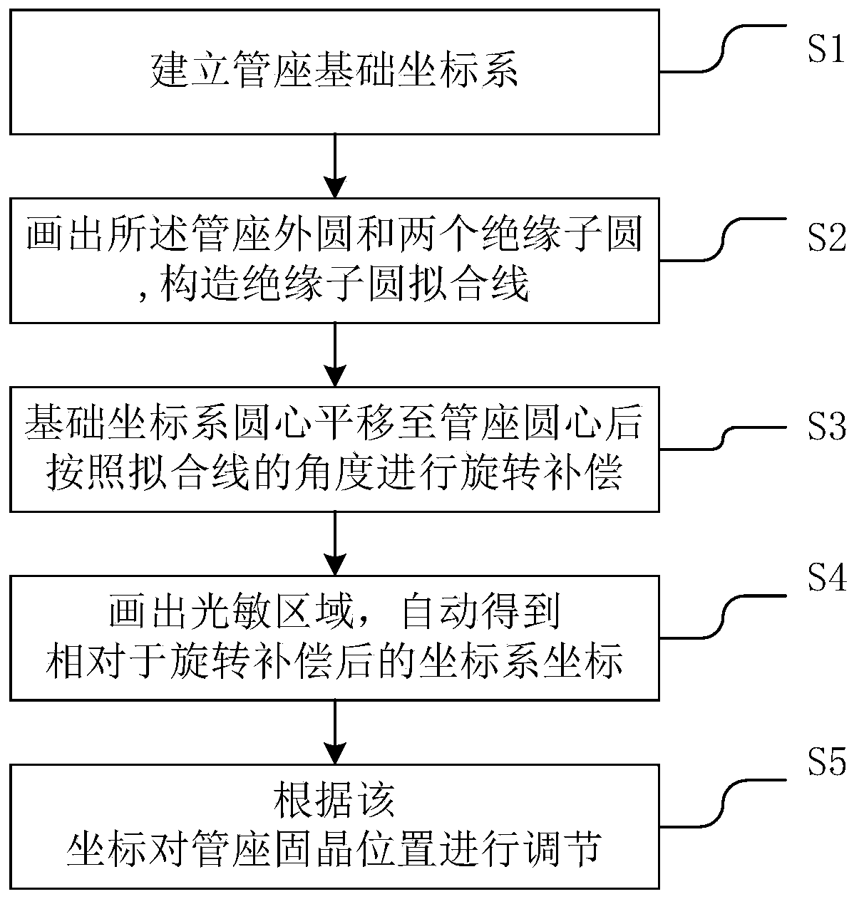
[0024] figure 1 It is a schematic flow chart of a measurement method for rotation compensation of a two-dimensional coordinate system according to an embodiment of the present invention; figure 1 shown, including the following steps:

[0025] S1, establishing the basic coordinate system of the pipe seat; specifically, drawing a line with the X-a...


PUM


Abstract

The invention relates to the technical field of transistor type packaging, in particular to a two-dimensional coordinate system rotation compensation measurement method. The method comprises the stepsof establishing a basic coordinate system of a tube base; drawing lines by using an X-axis side line and a Y-axis side line of a clamp, and taking focuses of the X-axis side line and the Y-axis sideline as original points; drawing an outer circle of the tube base and two insulator circles of the tube base; connecting the circle centers of the two insulator circles to construct a fitting line; translating the circle center of the basic coordinate system of the tube base to the circle center of the tube base, rotating the basic coordinate system of the tube base according to the angle of the fitting line, and storing a coordinate system obtained after rotation compensation; and drawing a chip photosensitive area of the tube base, and obtaining a coordinate position of the photosensitive area relative to the coordinate system after rotation compensation according to a coordinate algorithm; and adjusting the die bonding position of the tube base according to the coordinate position of the photosensitive area relative to the coordinate system obtained after rotation compensation. According to the embodiment of the invention, coordinate system rotation compensation is applied, and theaccuracy of TO product chip die bonding is ensured to the maximum extent.

Description

technical field [0001] The invention relates to the technical field of transistor packaging, in particular to a method and device for measuring rotation compensation of a two-dimensional coordinate system. Background technique [0002] Semiconductor TO-CAN (transistor package) has the advantages of small size, light weight, high efficiency, long life, easy modulation and low price, and has been widely used in industrial, medical and military fields, such as material processing, optical fiber communication, Laser ranging, target indication, laser guidance, laser radar, space optical communication, etc. With the continuous development of semiconductor TO-CAN (transistor package) in various application fields, the requirements for the placement accuracy of semiconductor TO-CAN (transistor package) products are getting higher and higher. [0003] At present, the measurement of TO package die-bonding placement has always been measured with the mechanical coordinate system of the...

Claims


Application Information

Patent Timeline
Patent Type & Authority Applications(China)
IPC IPC(8): H01L21/66
CPCH01L22/12
Inventor 龚成文温永阔胡靖
Owner 武汉东飞凌科技有限公司
Learn More