Connector detection equipment, detection method and production line

A technology of testing equipment and testing methods, applied in the direction of instruments, measuring electronics, measuring devices, etc., can solve the problems that the detection accuracy cannot reach 100%, increase the production cost, and the number of products is large, so as to reduce the cost of loading and unloading time, increase accuracy, and high degree of automation

Pending Publication Date: 2020-04-21
河南金华电气有限公司
View PDF0 Cites 1 Cited by
  • Summary
  • Abstract
  • Description
  • Claims
  • Application Information

AI Technical Summary

Problems solved by technology

[0003] The production scheme of the prior art is that quality inspectors identify quality problems such as missing pins, missing pins, and crooked pins connected to the car with the naked eye. This detection method has the following problems: (1) Passing personnel inspections, it is difficult to be affected by personal emotions, eye fatigue, etc. Due to the influence of control factors, there may be missed inspections, wrong inspections, etc., resulting in a detection accuracy rate that cannot reach 100%; (2) Due to the large number of products, each quality inspector needs to use visual inspection for each pin of each product , the efficiency is low, and the production cost is increased; (3) During the inspection process, the quality inspectors will repeatedly inspect the same product due to reasons such as product placement and personnel negligence, which increases the production cost

Method used


Image

  • Connector detection equipment, detection method and production line
  • Connector detection equipment, detection method and production line
  • Connector detection equipment, detection method and production line

Examples


Embodiment Construction

[0029] The following will clearly and completely describe the technical solutions in the embodiments of the present invention with reference to the accompanying drawings in the embodiments of the present invention. Obviously, the described embodiments are only some, not all, embodiments of the present invention. Based on the embodiments of the present invention, all other embodiments obtained by persons of ordinary skill in the art without creative efforts fall within the protection scope of the present invention.

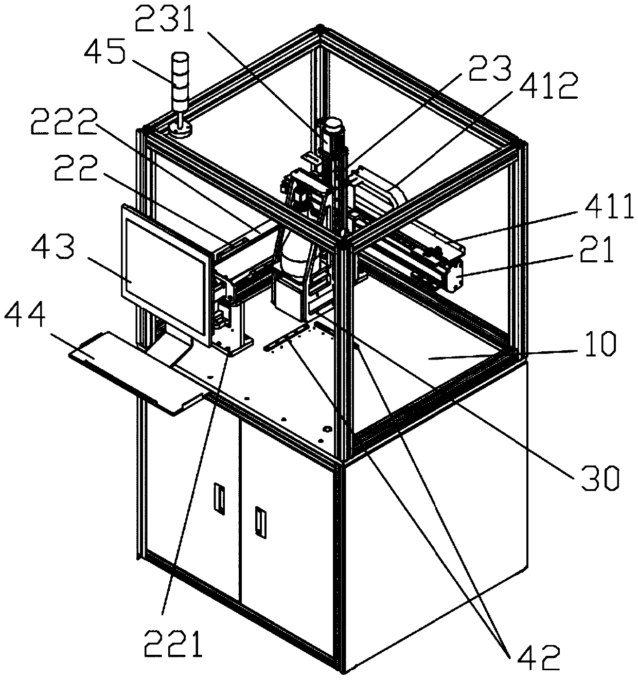
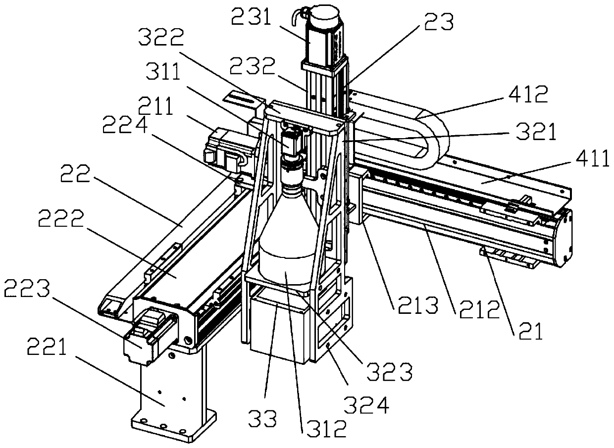
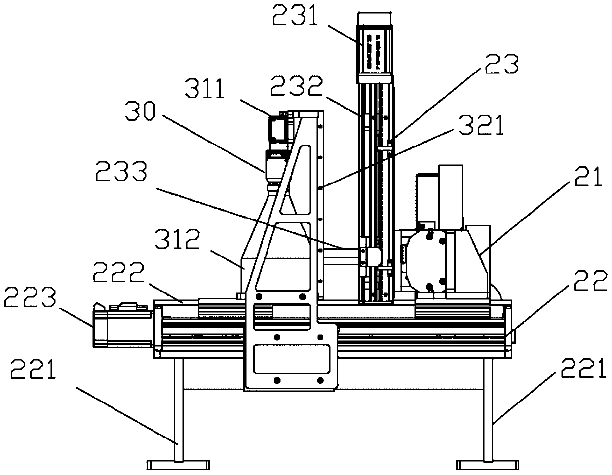
[0030] Such as Figure 1 to Figure 4 As shown, in one embodiment, a connector detection device is proposed, including: a support mechanism 10 for placing a connector, a controller, and an X-axis motion mechanism 21 above the support mechanism 10, a Y-axis A motion mechanism 22, a Z-axis motion mechanism 23, and a camera mechanism 30 for photographing the pins of the connector;

[0031] The Z-axis motion mechanism 23 is connected with the camera mechanism 30 to dri...


PUM


Abstract

An embodiment of the invention discloses connector detection equipment, a detection method and a production line. The connector detection equipment comprises a supporting mechanism used for accommodating a connector, a controller, an X-axis movement mechanism, a Y-axis movement mechanism, a Z-axis movement mechanism and a camera shooting mechanism used for shooting a contact pin of the connector,wherein the X-axis movement mechanism, the Y-axis movement mechanism and the Z-axis movement mechanism are located above the supporting mechanism; the Z-axis movement mechanism is connected with the camera shooting mechanism so as to drive the camera shooting mechanism to move back and forth in the Z-axis direction; the X-axis movement mechanism is connected with the Z-axis movement mechanism so as to drive the Z-axis movement mechanism and the camera shooting mechanism to move back and forth in the X-axis direction; the Y-axis movement mechanism is connected with the X-axis movement mechanismso as to drive the X-axis movement mechanism, the Z-axis movement mechanism and the camera shooting mechanism to move back and forth in the Y-axis direction; and the controller is electrically connected with the X-axis movement mechanism, the Y-axis movement mechanism, the Z-axis movement mechanism and the camera shooting mechanism. The connector detection equipment is high in automation degree,improves the detection accuracy, improves the detection efficiency, and reduces the production cost.

Description

technical field [0001] The invention relates to the technical field of connector detection, in particular to a connector detection device, a detection method and a production line. Background technique [0002] As a common part of mechanical equipment, the quality of connectors seriously affects the quality of mechanical equipment, and the quality of connector pins is crucial to the quality of the entire connector. During the production process of the connector, there may be quality problems such as crooked pins, missing pins, and missing pins. Therefore, it is necessary to accurately detect the pins of the connector. [0003] The production scheme of the prior art is that quality inspectors identify quality problems such as missing pins, missing pins, and crooked pins connected to the car with the naked eye. This detection method has the following problems: (1) Passing personnel inspections, it is difficult to be affected by personal emotions, eye fatigue, etc. Due to the ...

Claims


Application Information

Patent Timeline
Patent Type & Authority Applications(China)
IPC IPC(8): G01R31/01G01N21/88H01R43/20
CPCG01N21/88G01R31/013H01R43/20
Inventor 张金华
Owner 河南金华电气有限公司
Why Eureka
Try Eureka