Water seepage alarm device at the top of underground engineering

An alarm device and underground engineering technology, which is applied to alarms, instruments, liquid tightness measurement using liquid/vacuum degree, etc. It can solve the problems that the underground space cannot be monitored in real time for a long time

Active Publication Date: 2021-05-11
日照市建筑设计研究院有限公司
View PDF11 Cites 0 Cited by
  • Summary
  • Abstract
  • Description
  • Claims
  • Application Information

AI Technical Summary

Problems solved by technology

[0004] The purpose of the present invention is to solve the shortcomings in the prior art that the existing equipment adopts the method of regional sampling for simulation inspection, and cannot monitor the underground space in real time for a long time during the construction period, and proposes a water seepage alarm device at the top of the underground project

Method used


Image

  • Water seepage alarm device at the top of underground engineering
  • Water seepage alarm device at the top of underground engineering
  • Water seepage alarm device at the top of underground engineering

Examples


Embodiment 1

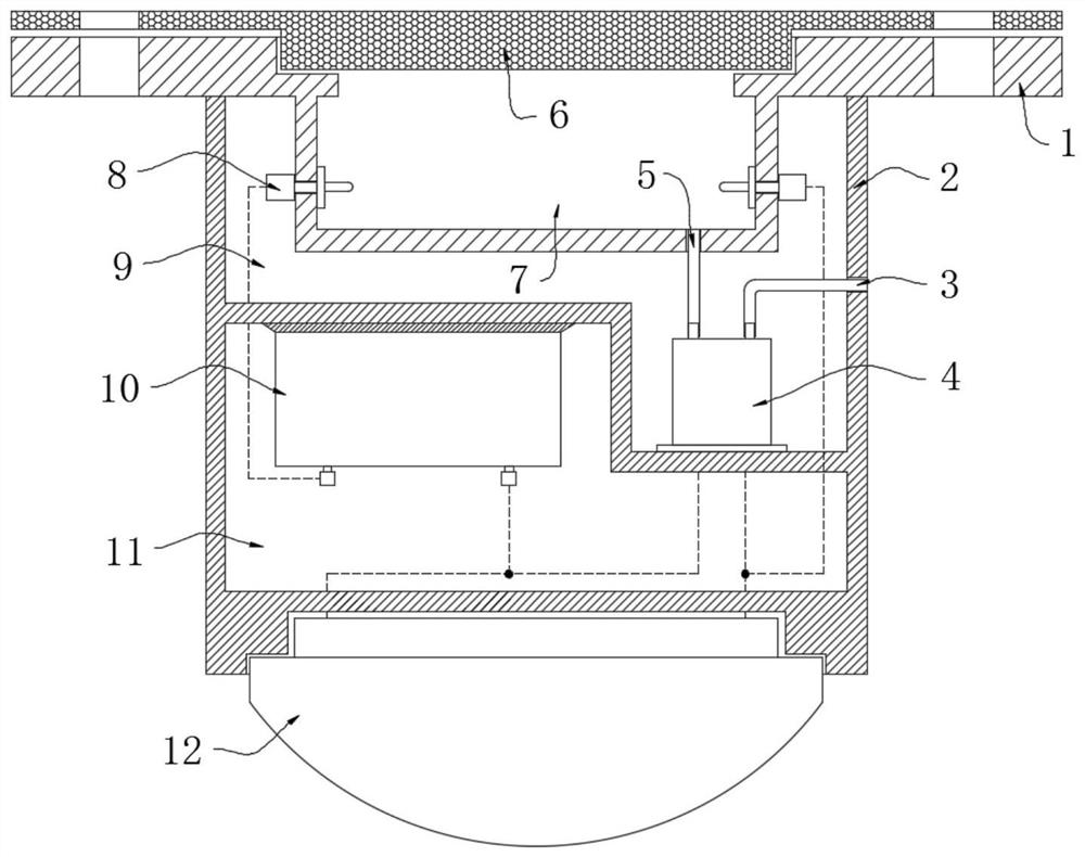
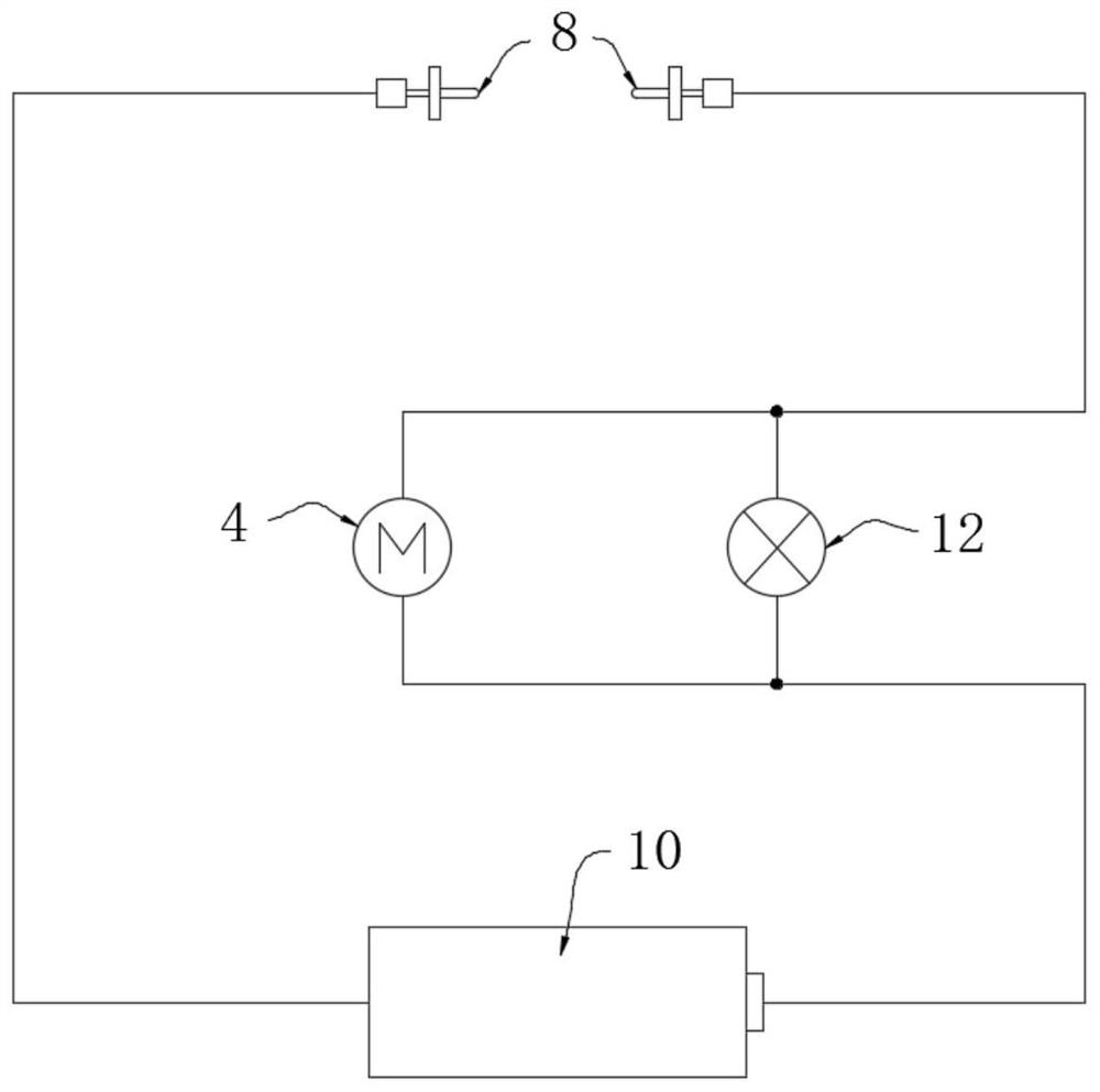
[0027] refer to Figure 1-2 , a water seepage alarm device at the top of an underground project, comprising a mounting plate 1, the upper end of the mounting plate 1 is embedded with a water-absorbing pad 6, the mounting plate 1 is provided with a water storage tank 7, and on the outer wall of the water storage tank 7 A conductive detection head 8 is inserted symmetrically and sealed. The mounting plate 1 is covered with a detection cover 2. A warning light 12 is installed at the lower end of the detection cover 2. The detection cover 2 includes a detection cavity 9 and a power cavity 11. A water pump 4 is fixedly installed on the inner bottom wall of the detection chamber 9, and a water pump 5 and a drain pipe 3 are respectively installed on the water pump 4, and the water suction pipe 5 is inserted to communicate with the water storage tank 7, and the upper part of the power chamber 11 A storage battery 10 is fixedly installed on the top wall.

[0028] Preferably, the two c...

Embodiment 2

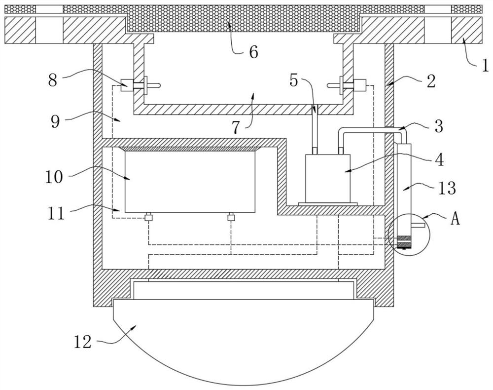
[0032] refer to Figure 3-5 , a water seepage alarm device at the top of an underground project, which is basically consistent with Embodiment 1, the difference is that:

[0033] A retention pipe 13 is fixedly installed on the side wall of the detection cover 2, and one end of the drainage pipe 3 extends to the outside of the detection cover 2 and is sealed and inserted in the retention pipe 13. The lower end of the inner wall of the retention pipe 13 is Two annular metal sheets 15 are embedded in sequence, and the retention pipe 13 is located at the upper end of the two annular metal sheets 15, and an overflow pipe 14 is inserted and communicated with, and the lower end of the retention pipe 13 is plugged with a drain plug 16;

[0034] The water pump 4 discharges the water in the water storage tank 7 into the stagnation pipe 13 through the drain pipe 3, so that the water level in the stagnation pipe 13 continues to rise, so that the two annular metal sheets 15 are conducted, ...


PUM


Abstract

The invention discloses an alarm device for water seepage at the top of an underground project, which comprises a mounting plate, a water-absorbing pad is embedded in the upper end of the mounting plate, a water storage tank is opened on the mounting plate, and a symmetrical seal is inserted on the outer wall of the water storage tank. A conductive detection head is provided, a detection cover is provided on the mounting plate, a warning light is installed at the lower end of the detection cover, the detection cover includes a detection cavity and a power cavity, and the inner bottom wall of the detection cavity is fixedly installed There is a water pump, and the water pump is respectively equipped with a suction pipe and a drain pipe, and the water suction pipe is inserted to communicate with the water storage tank. In the present invention, the first circuit is conducted through two conductive detection heads, the warning light flickers through the water absorption of the water-absorbing pad and the drainage of the water pump, and the second circuit is formed by self-locking of two ring-shaped metal sheets to realize continuous drainage of large seepage water And continuous alarm, through the distributed installation of multiple devices to achieve the effect of long-term and large-area real-time monitoring and alarm.

Description

technical field [0001] The invention relates to the field of underground engineering, in particular to a water seepage alarm device at the top of an underground engineering. Background technique [0002] Underground projects need to excavate tunnels or underground spaces during construction. The quality of underground space construction is particularly important. The water seepage phenomenon that occurs during the construction process needs to be repaired in time to avoid wasting a lot of manpower and financial resources after the completion of the project. It is difficult to maintain it , and the maintenance of the seepage roof after the completion of the project cannot completely solve the problem, it can only be checked and maintained regularly, which consumes manpower and financial resources. [0003] At present, the repair of water seepage phenomenon usually requires the construction personnel to find the obvious water seepage area, and then report for inspection and re...

Claims


Application Information

Patent Timeline
Patent Type & Authority Patents(China)
IPC IPC(8): G08B21/24G01M3/16
CPCG01M3/16G08B21/24
Inventor 何卫东
Owner 日照市建筑设计研究院有限公司
Why Eureka
Try Eureka