Automatic cooling device for relay

An automatic cooling and relay technology, which is applied in the directions of relay ventilation/cooling/heating, relay base/shell/cover, etc., can solve the problem of undetectable relay temperature, electronic components temperature characteristics, poor anti-interference ability of electronic circuits, and damaged relays And other issues

Inactive Publication Date: 2020-04-21
PUJIANG LECHENG ELECTRONICS TECH CO LTD
View PDF0 Cites 2 Cited by
  • Summary
  • Abstract
  • Description
  • Claims
  • Application Information

AI Technical Summary

Problems solved by technology

Existing relays cannot detect the temperature of the relay. Due to the large voltage drop of the tube, the power consumption and heat generation after conduction are also large, and the temperature characteristics of electronic components and the anti-interference ability of electronic circuits are poor. The normal temperature of the relay Between 20 and 40 degrees Celsius, when the temperature of the relay is too high, it will damage the relay and cause the relay to fail to work normally

Method used


Image

  • Automatic cooling device for relay
  • Automatic cooling device for relay
  • Automatic cooling device for relay

Examples


Embodiment Construction

[0015] All features disclosed in this specification, or steps in all methods or processes disclosed, may be combined in any manner, except for mutually exclusive features and / or steps.

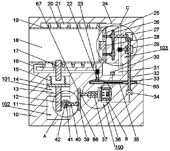
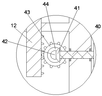
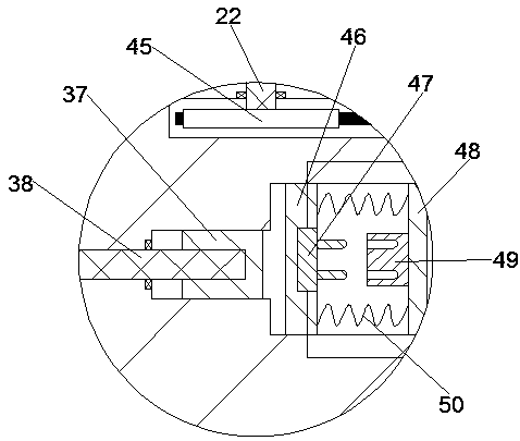
[0016] Combine below Figure 1-4 The present invention is described in detail, and for convenience of description, the orientations mentioned below are now stipulated as follows: figure 1 The up, down, left, right, front and back directions of the projection relationship itself are the same.

[0017] An automatic cooling device for a relay of the device of the present invention includes a base body 10, a mounting block 19 is provided in the base body 10, a placement cavity 18 is provided on the mounting block 19, and a cooling device is provided on the right side of the mounting block 19. Mechanism 104, a cooling cavity 21 is provided on the outside of the installation block 19, a spiral water pipe 20 is provided in the cooling cavity 21, a heat conduction cavity 13 is provided below the cool...


PUM


Abstract

The invention discloses an automatic cooling device for a relay. The automatic cooling device for the relay comprises a base body; a mounting block is arranged in the base body; a placing cavity is defined in the mounting block; a cooling mechanism is arranged on the right side of the mounting block; a cooling cavity is formed in the outer side of the mounting block; a spiral water pipe is arranged in the cooling cavity; a heat conduction cavity is formed below the cooling cavity; a heat conduction mechanism is arranged in the heat conduction cavity; a transmission cavity is formed below the heat conduction cavity; a transmission mechanism is arranged in the transmission cavity; a first rectangular groove is formed to the right side of the transmission cavity; a power supply groove is formed to the right side of the first rectangular groove; a power supply mechanism is arranged in the power supply groove; a second rectangular groove is formed above the power supply groove; a third rectangular groove is formed above the second rectangular groove; a fourth rectangular groove is formed above the third rectangular groove; and a power shaft penetrating through the third rectangular groove is rotatably arranged between the fourth rectangular groove and the second rectangular groove.

Description

technical field [0001] The invention relates to the technical field of relays, in particular to an automatic cooling device for relays. Background technique [0002] The relay is an electrical control module, which is an electrical appliance that causes the controlled quantity to undergo a predetermined step change in the electrical output circuit when the change of the input quantity meets the specified requirements. It has an interactive relationship between the control system and the controlled system, and plays the role of automatic adjustment, safety protection, conversion circuit, etc. in the circuit. Existing relays cannot detect the temperature of the relay. Due to the large voltage drop of the tube, the power consumption and heat generation after conduction are also large, and the temperature characteristics of electronic components and the anti-interference ability of electronic circuits are poor. The normal temperature of the relay Between 20 and 40 degrees Celsi...

Claims


Application Information

Patent Timeline
IPC IPC(8): H01H45/12H01H45/02
CPCH01H45/02H01H45/12
Inventor 不公告发明人
Owner PUJIANG LECHENG ELECTRONICS TECH CO LTD
Why Eureka
Try Eureka