
A side groove gluing device for processing photovoltaic solar panels and its working method

A photovoltaic solar energy and solar panel technology, which is applied in the field of side tank gluing equipment, can solve the problems of low degree of automation, small area and small range of side tank gluing equipment

Active Publication Date: 2021-04-27
晟高发新能源发展(江苏)有限公司
View PDF7 Cites 0 Cited by
  • Summary
  • Abstract
  • Description
  • Claims
  • Application Information

AI Technical Summary

Problems solved by technology

[0005] The purpose of the present invention is to solve the problem that the existing side groove gluing equipment for photovoltaic solar panel processing has a low degree of automation, is time-consuming and laborious to use, and is very inconvenient to operate; the area covered by the side groove gluing equipment is small; The working position of gluing and gluing on the side groove of the solar panel on the opposite side is not accurate enough; the efficiency of the side groove gluing equipment on the side groove of the board groove is slow; and the glue coverage on the side groove of the solar panel core is not uniform and smooth , leading to poor quality of gluing equipment for photovoltaic solar panels on side grooves; and poor stability of side groove gluing equipment when clamping and moving solar panels; and side groove gluing equipment can only be used for the same width and thickness Solar panel clamping and gluing processing, the problem of the narrow range of work adaptation of the side groove gluing equipment, and a side groove gluing equipment and its working method for photovoltaic solar panel processing are proposed

Method used


Image

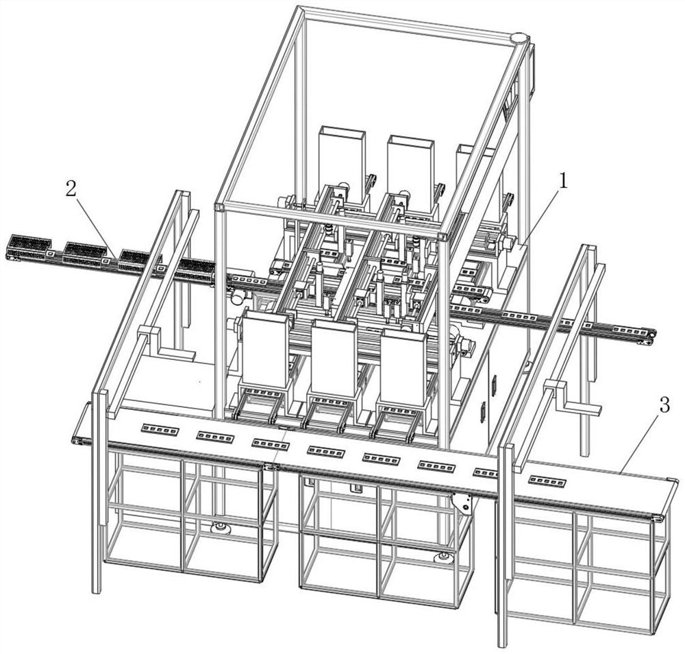
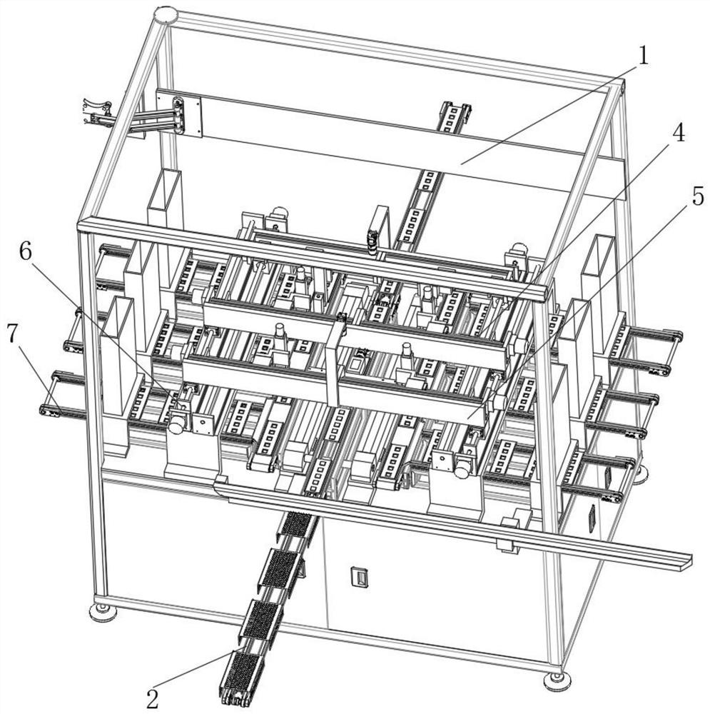
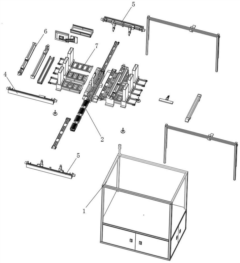
  • A side groove gluing device for processing photovoltaic solar panels and its working method
  • A side groove gluing device for processing photovoltaic solar panels and its working method
  • A side groove gluing device for processing photovoltaic solar panels and its working method

Examples


Embodiment Construction

[0048] The technical solutions of the present invention will be clearly and completely described below with reference to the embodiments. Obviously, the described embodiments are only a part of the embodiments of the present invention, rather than all the embodiments. Based on the embodiments of the present invention, all other embodiments obtained by those of ordinary skill in the art without creative efforts shall fall within the protection scope of the present invention.

[0049] see Figure 1-12 As shown in the figure, a side groove gluing equipment for photovoltaic solar panel processing includes a worktable 1, an inner conveying table 2 and an end conveying table 3. An inner conveying table 2 is horizontally arranged above the middle of the worktable 1, and the worktable 1 An end conveying table 3 is horizontally arranged at the edges of both sides;

[0050] A catch tray 4 is vertically arranged in the upper middle of the worktable 1, and glue trays 5 are provided on bo...


PUM


Abstract

The invention discloses a side groove gluing equipment for processing photovoltaic solar panels and a working method thereof. An end conveying platform is arranged horizontally at the edges on both sides of the table, and a pick-and-feed tray is vertically arranged in the middle above the worktable. The beneficial effects of the present invention are: the motor one drives the gear one to roll in the rolling groove to drive the solar panel to move, and the solar panel is placed on the side conveying table to continue conveying, and the motor three on the rubber plate moves on the roller one , to drive the vertical seat to adjust left and right to move to the top of the edge of the solar panel core, the motor five in the movable seat rolls on the rolling rail through the gear two, to drive the rubber outlet to adjust up and down, and the rubber outlet is close to the panel of the solar panel The edge of the core, the glue in the glue barrel flows out from the dispensing hole, and the edge of the core is glued and reinforced. The equipment has a high degree of automation and saves time and effort.

Description

technical field [0001] The invention relates to a side groove gluing device, in particular to a side groove gluing device used for photovoltaic solar panel processing and a working method thereof, and belongs to the application technical field of the edge groove gluing device. Background technique [0002] During the processing of photovoltaic solar panels, the panel core is generally embedded in the panel groove of the solar panel. The panel core mainly controls the integrated circuits on the solar panel, and some panel cores are also integrated with power storage panels. [0003] The main function of the edge slot gluing equipment is to glue and reinforce the edge slot of the panel slot after the panel core is placed in the panel slot of the solar panel to ensure the tightness of the panel core and the solar panel assembly. [0004] The existing side groove gluing equipment for photovoltaic solar panel processing still has many deficiencies in use. The existing side groove...

Claims


Application Information

Patent Timeline
Patent Type & Authority Patents(China)
IPC IPC(8): H01L31/048H01L31/18
CPCH01L31/048H01L31/186Y02E10/50Y02P70/50
Inventor 王光银王善波华新方江川田朝义
Owner 晟高发新能源发展(江苏)有限公司
Learn More