Low-voltage switch cabinet capable of slowing down push-in

A low-voltage switchgear, a pair of technology, applied in the direction of pull-out switchgear, switchgear, electrical components, etc., can solve the problem of damage to the primary plug-in and secondary plug-in, achieve the effect of convenient repair and maintenance, and avoid damage

Active Publication Date: 2020-04-21
江门冠德电器制品有限公司
View PDF4 Cites 1 Cited by
  • Summary
  • Abstract
  • Description
  • Claims
  • Application Information

AI Technical Summary

Problems solved by technology

[0003] The purpose of the present invention is to provide a low-voltage switchgear that slows down the push-in in view of the technical problem tha

Method used


Image

  • Low-voltage switch cabinet capable of slowing down push-in
  • Low-voltage switch cabinet capable of slowing down push-in
  • Low-voltage switch cabinet capable of slowing down push-in

Examples


Example Embodiment

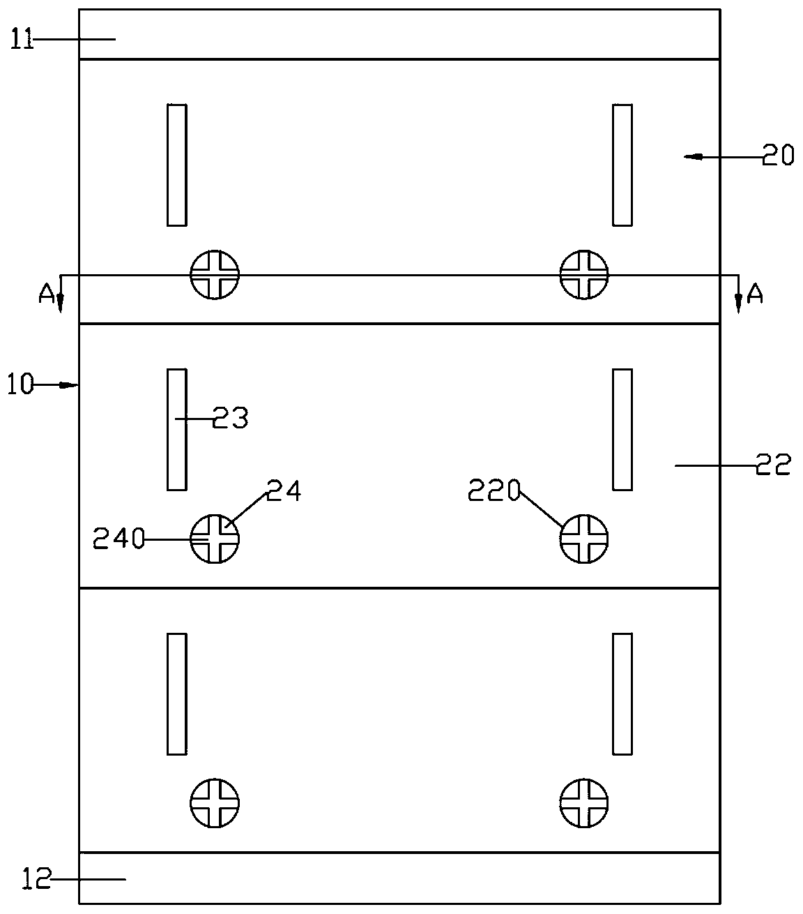
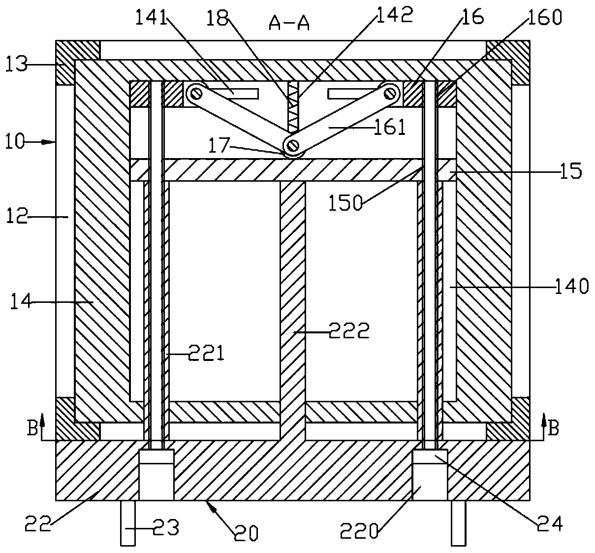
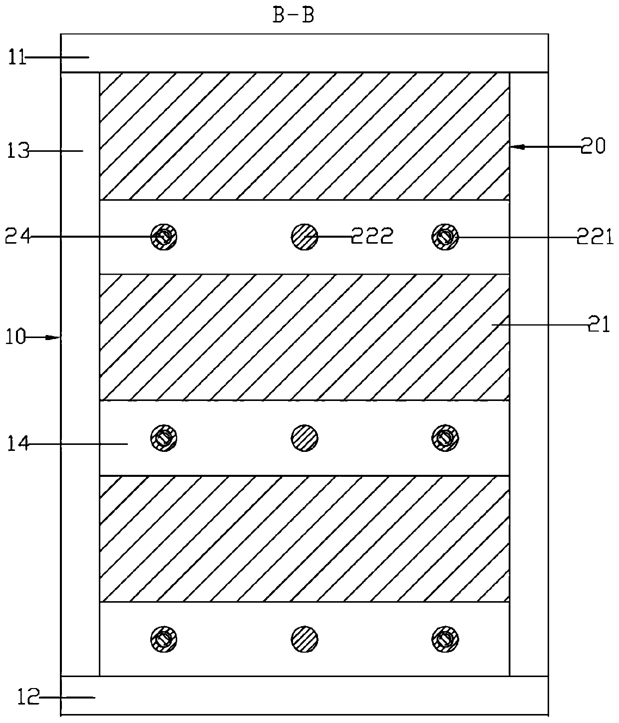
[0016] Such as Figure 1 ~ Figure 3 As shown, a low-voltage switchgear that slows down push-in includes a cabinet body 10 and a number of drawers 20; the cabinet body 10 includes a frame; a number of horizontal isolation panels 14 distributed up and down are arranged inside the frame; The upper end surface of the isolating plate 14; the horizontal isolating plate 14 is formed with a moving guide groove 140; the rear end of the upper and lower side walls of the moving guide groove 140 is provided with a pair of symmetrically arranged buffering left and right moving blocks 16, and the middle rear is elastic The sliding is provided with a buffer front and rear moving block 17; the adjacent ends of the pair of buffer left and right shift blocks 16 are respectively hinged with a connecting rod 161; the other end of the connecting rod 161 is hinged on the buffer front and rear moving block 17; the buffer front and rear moving blocks 17 are located in a pair of buffers The front side ...


PUM


Abstract

The invention discloses a low-voltage switch cabinet capable of slowing down push-in. A pair of buffering left-right moving blocks which are distributed symmetrically in a left-and-right direction arearranged at the rear ends of the upper side wall and the lower side wall of a moving guide groove in a left-right sliding mode; buffering front-back moving blocks are arranged on the rear portion ofthe middle of the moving guide groove in a front-back elastic sliding mode; connecting rods are hinged to the ends, close to each other, of the buffering left-right moving blocks; the other ends of the connecting rods are hinged to the buffering front-back moving blocks respectively; a pair of side guide rods arranged in a bilateral symmetry mode and located at the lower side of a drawer body is formed on the rear end face of a drawer panel; fixing bolts penetrate through the drawer panel and the side guide rods from front to back and are connected to the drawer panel and the side guide rods in a threaded mode; a pair of front limiting threaded holes which are matched with the fixing bolts on corresponding sides and are through in a front-and-back direction is formed in a buffering supporting plate; and rear limiting threaded holes which are matched with the fixing bolts on corresponding sides and are through in a front-and-back direction is formed in the buffering left-right moving blocks.

Description

technical field [0001] The invention relates to the field of low-voltage switch cabinets, in particular to a low-voltage switch cabinet that slows down push-in. Background technique [0002] Low-voltage switchgear is suitable for power plants, substations, petrochemical, metallurgical and steel rolling and other factories and mines, residential quarters, high-rise buildings and other places, as the power conversion and distribution system of AC power supply frequency 50 to 60Hz, rated working voltage AC 660V and below Used for consumer equipment control. At present, the structure of low-voltage switchgear is relatively simple, and the drawer body of low-voltage switchgear generally adopts the impact type, which is easy to cause damage to the primary plug-in and secondary plug-in on the drawer body, affecting the normal use of low-voltage switchgear. Contents of the invention [0003] The purpose of the present invention is to provide a low-voltage switchgear that slows do...

Claims


Application Information

Patent Timeline
IPC IPC(8): H02B11/127H02B11/173
CPCH02B11/127H02B11/173
Inventor 徐杰
Owner 江门冠德电器制品有限公司
Why Eureka
Try Eureka