Motor rotor and reluctance motor

A motor rotor and reluctance technology, applied in the magnetic circuit, electric components, electrical components, etc., can solve the problems of motor performance decline, limit the use range of the motor, increase and decrease the output torque of the motor, etc. The effect of large use range and torque increase

Active Publication Date: 2020-04-21
GREE ELECTRIC APPLIANCES INC
View PDF6 Cites 3 Cited by
  • Summary
  • Abstract
  • Description
  • Claims
  • Application Information

AI Technical Summary

Problems solved by technology

However, for this solution, due to the offset placement of the permanent magnets, the torque density of the permanent magnets is biased. When the motor rotates in one direction, the torque output of the motor can be effectively improved. When the motor rotates in both directions, the In one of the directions, the increase in the output torque of the motor will be greatly reduced, resulting in a significant decrease in the performance of the motor, which seriously limits the scope of use of the motor

Method used


Image

  • Motor rotor and reluctance motor
  • Motor rotor and reluctance motor
  • Motor rotor and reluctance motor

Examples


Embodiment Construction

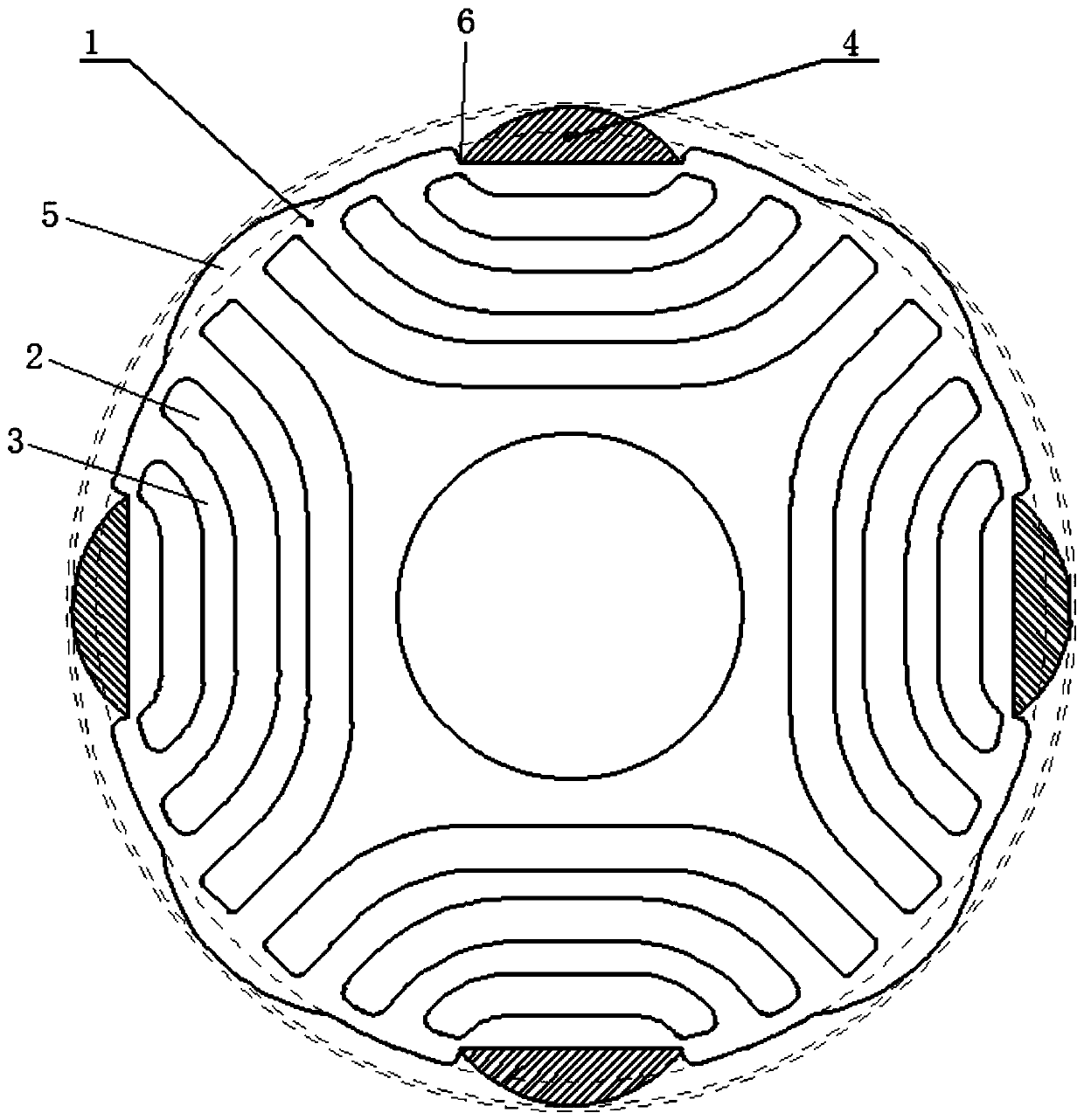
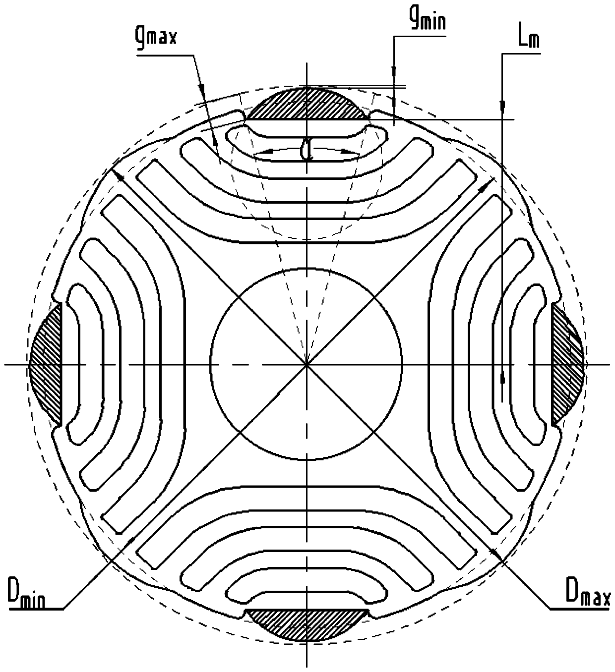
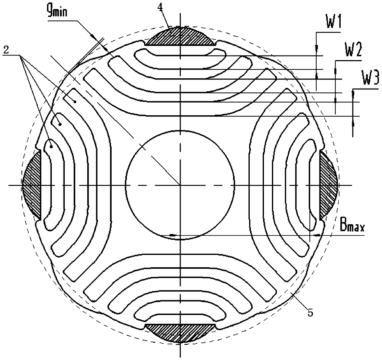
[0027] see in conjunction Figure 1 to Figure 5 As shown, according to the embodiment of the present application, the motor rotor includes a rotor core 1, and the rotor core 1 includes a plurality of magnetic barrier groups arranged in the circumferential direction, and each magnetic barrier group includes at least two magnetic barrier groups arranged at intervals in the radial direction. Through barriers 2, a magnetic conduction channel 3 is formed between adjacent magnetic flux barriers 2, and a radially magnetized permanent magnet 4 is attached to the outer peripheral wall of the rotor core 1. Under the same pole, the d-axis of the permanent magnet 4 is aligned with the The reluctance q-axis coincides.

[0028] In this application, the position of the permanent magnet 4 arranged on the outer peripheral wall of the rotor core 1 is optimized so that the d-axis of the permanent magnet 4 coincides with the reluctance q-axis, so that the permanent magnet 4 can be located on the ...


PUM


Abstract

The invention provides a motor rotor and a reluctance motor. The motor rotor comprises a rotor core (1), wherein the rotor core (1) includes a plurality of magnetic barrier groups arranged in a circumferential direction, each magnetic barrier group includes at least two magnetic flux barriers (2) arranged at intervals in a radial direction, a magnetic conduction channel (3) is formed between everytwo adjacent magnetic flux barriers (2), a radially magnetized permanent magnet (4) is attached to an outer circumferential wall of the rotor core (1), and a d axis of the permanent magnet (4) and areluctance q axis coincide under a same pole. According to the motor rotor, an output torque of the motor can be effectively improved in a bidirectional rotation process of the motor, working performance of the motor is increased, and an application range of the motor is enlarged.

Description

technical field [0001] The present application relates to the technical field of motor equipment, in particular to a motor rotor and a reluctance motor. Background technique [0002] At present, asynchronous motor systems are mostly used in the field of electrical transmission. Compared with asynchronous motor systems, permanent magnet motor systems have the characteristics of low loss and high efficiency, which is the development trend of the next generation of transmission systems. Due to the high back electromotive force of ordinary permanent magnet synchronous motors, there is a danger of damaging the inverter during high-speed operation, so permanent magnet assisted synchronous reluctance motors are favored. [0003] The synchronous reluctance motor has high reliability, because there is no permanent magnet on the rotor, so there is no risk of loss of magnetism, but the low power factor is a major shortcoming of the synchronous reluctance motor, which requires the inver...

Claims


Application Information

Patent Timeline
Patent Type & Authority Applications(China)
IPC IPC(8): H02K1/27H02K29/03
CPCH02K1/27H02K29/03H02K2201/03H02K2213/03
Inventor 黎永材陈彬胡余生童童张健
Owner GREE ELECTRIC APPLIANCES INC
Why Eureka
Try Eureka