
Spring plate

A spring plate, vehicle suspension technology, applied in springs, vehicle springs, springs/shock absorbers, etc., can solve problems such as complex structures

Active Publication Date: 2020-04-21
THYSSENKRUPP BILSTEIN +1
View PDF5 Cites 0 Cited by
  • Summary
  • Abstract
  • Description
  • Claims
  • Application Information

AI Technical Summary

Problems solved by technology

This structure is quite complex

Method used


Image

  • Spring plate
  • Spring plate

Examples


Embodiment Construction

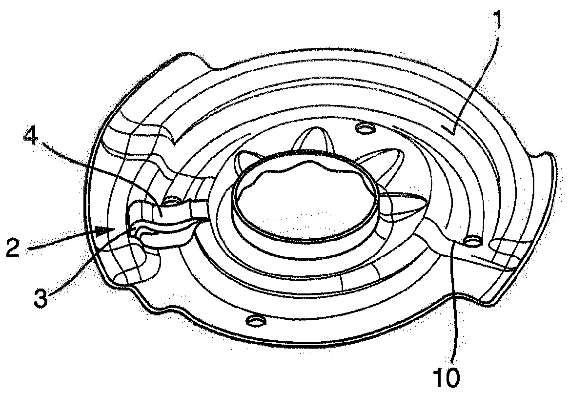
[0017] figure 1 A spring plate according to the invention is shown, wherein the surface 1 facing the vehicle suspension spring (not shown) is shown in perspective. The surface 1 has an end stop 10 on which the end face of the vehicle suspension spring formed as a helical compression spring is supported during operation. Furthermore, there is a region 3 extending from the spring plate material and forming a defined support point for a vehicle suspension spring (not shown). In the exemplary embodiment shown, the spring plate is produced from a sheet metal semi-finished product by forming, and the extension area is also produced by forming.

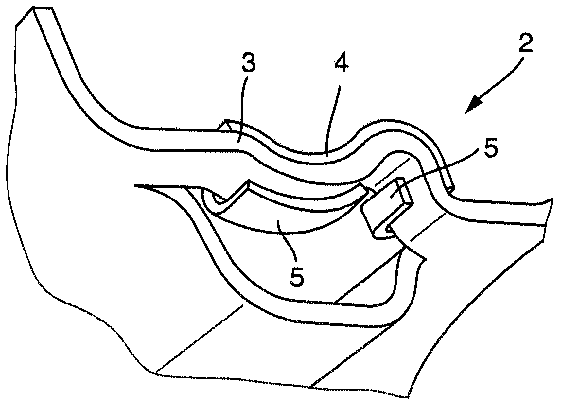
[0018] The extension area 3 has the form of a bridge and supports a sheet metal element 4 acting as a corrosion protection element. Thus, the sheet metal element 4 is arranged on the support point 2 and is in contact with the spring in all operating states, ie in particular in all spring deflection states of the vehicle suspension spring. ...


PUM


Abstract

The invention relates to a spring plate for supporting a vehicle support spring, having a surface (1), which faces the vehicle support spring, and at least one supporting point (2), wherein the springplate has a region (3) which is set out from the surface (1) in the direction of the vehicle support spring and which forms the supporting point (2), and wherein a sheet metal element (4) acting as acorrosion protection element is fastened to the set-out region (3) and is in contact with the vehicle support spring in all operating states.

Description

technical field [0001] The invention relates to a spring plate for supporting a vehicle suspension spring, as for example used in a suspension strut for a motor vehicle. Background technique [0002] In the case of sprung shock absorbers and McPherson suspension struts, the body springs (vehicle suspension springs) are usually supported on spring plates fastened to the shock absorber tubes. Coating of vehicle suspension springs to protect them from corrosion. During actuation, relative motion occurs between the spring and the spring plate as the spring deflects and rebounds, and causes damage to the coating of the spring. Springs with damaged coatings are susceptible to corrosion. Vehicle suspension springs are exposed to dirt and moisture in the wheel suspension area, which promotes undesired corrosion. [0003] In order to reduce the risk of corrosion, DE 10 2005 021 765 A1 proposes a bearing device for vehicle springs, which comprises a spring plate with a plurality of...

Claims


Application Information

Patent Timeline
IPC IPC(8): F16F1/12
CPCB60G11/14B60G15/063B60G2202/12B60G2204/12422B60G2206/7104B60G2206/8101B60G2206/81012F16F1/126F16F2230/0023B60G11/16B60G2204/124
Inventor 克劳斯·施密特安德里斯·麦伊
Owner THYSSENKRUPP BILSTEIN
Learn More