Head-up display device and image projection unit

A head-up display and image technology, applied in the direction of instruments, polarizing elements, optical elements, etc., can solve the problems of reduced brightness and insufficient guarantee

Inactive Publication Date: 2020-04-21
DENSO CORP +1
View PDF14 Cites 0 Cited by
  • Summary
  • Abstract
  • Description
  • Claims
  • Application Information

AI Technical Summary

Problems solved by technology

In this case, the size of the direction corresponding to the left-right direction of the image of the visually recognizable area cannot be sufficiently ensured, or conversely, the illumination light is diffused more than necessary in the direction...

Method used


Image

  • Head-up display device and image projection unit
  • Head-up display device and image projection unit
  • Head-up display device and image projection unit

Examples


no. 1 approach

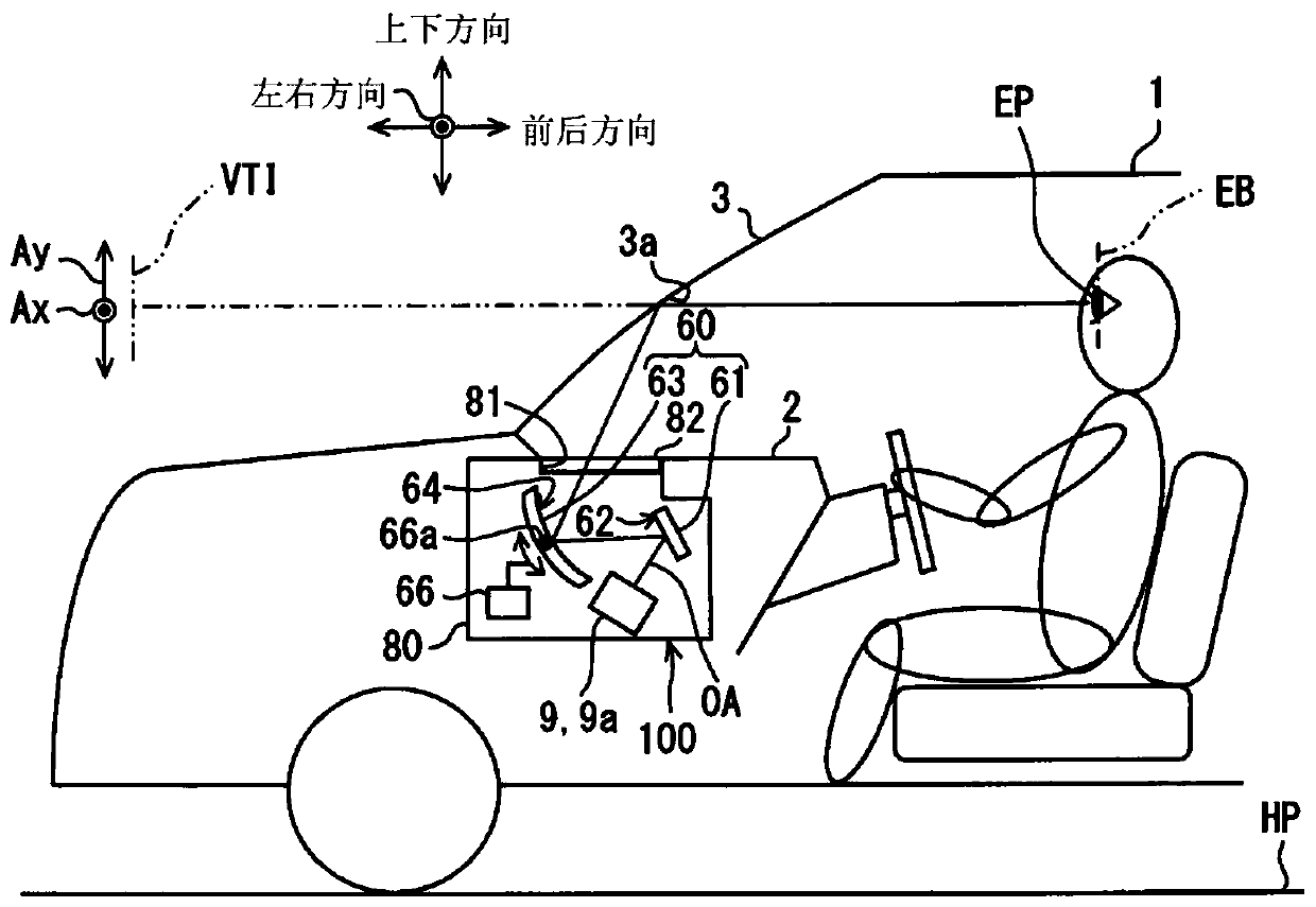
[0041] Such as figure 1 As shown, the head-up display device 100 according to the first embodiment of the present disclosure is mounted on a vehicle 1 and housed in a dashboard 2 . Here, a vehicle is broadly understood to include vehicles such as airplanes and ships in addition to automobiles and railway vehicles. The HUD device 100 projects image display light onto the windshield 3 as projection means of the vehicle 1 . As a result, the HUD device 100 displays the image as a virtual image VTI that the passenger can visually recognize. That is, the display light reflected by the windshield 3 reaches the indoor visual recognition area EB of the vehicle 1 , and the occupant whose eyepoints EP of both eyes are located in the visual recognition area EB perceives the light. Also, the passenger can recognize various information displayed as the virtual image VTI. Examples of various information displayed as the virtual image VTI include information related to the running of the v...

no. 2 approach

[0104] Such as Figure 11 , 12 As shown, the second embodiment is a modified example of the first embodiment. The second embodiment will be described focusing on differences from the first embodiment.

[0105] The anisotropic diffusion part 220 of the second embodiment further includes a polarizing element layer 228 . The polarizing element layer 228 is stacked on the isotropic diffusion layer 221 and the anisotropic prism array layer 223 to restrict transmission of predetermined polarized light.

[0106] Specifically, the polarizing element layer 228 of this embodiment is a reflective deflection element using a wire grid. The polarizing element layer 228 is formed in a sheet shape and has a plurality of metal wires extending in a direction perpendicular to the transmission axis TA of the polarizing plate 50 d on the incident side in the image display panel 50 . The plurality of metal wires are made of, for example, aluminum or the like, and are arranged in parallel with e...


PUM


Abstract

A head-up display device, which displays an image as a virtual image (VTI) by projecting and reflecting image display light of the image onto a projection member (3), is provided with: an illuminationlight source unit (10) for emitting illumination light; an image forming unit (50) for forming an image by partial transmission of the illumination light and emitting the image as display light; andanisotropic diffusion units (20, 220) disposed on an optical path between the illumination light source unit (10) and the image forming unit (50) and diffusing the illumination light at an anisotropicdiffusion angle. When the image is displayed as a virtual image, if an image vertical axis (Ay) is defined as a direction along the vertical direction of a vehicle in the image, and an image horizontal axis (Ax) is defined as a direction perpendicular to the image vertical axis (Ay) in the image, in the anisotropic diffusion units, a divergence angle in a direction (LDd) corresponding to the image horizontal axis (Ax) of the image is larger than a divergence angle in a direction (SDd) corresponding to the image vertical axis (Ay).

Description

[0001] Cross References to Related Applications [0002] This application is based on Japanese Patent Application No. 2017-172396 filed on September 7, 2017, and its content is cited here. technical field [0003] The present disclosure relates to a head-up display device (hereinafter, simply referred to as a HUD device) and an image projection unit. Background technique [0004] Conventionally, a HUD device and an image projection unit used in the HUD device are known. The HUD device is mounted on a vehicle and displays an image as a passenger by projecting display light of an image onto a projection member and reflecting the display light. A virtual image that can be visually confirmed. The image projection unit disclosed in Patent Document 1 includes an illumination light source unit, an image forming unit, and a diffusion unit. The illumination light source unit emits illumination light. The image forming unit forms an image by partially transmitting the illumination ...

Claims


Application Information

Patent Timeline
IPC IPC(8): G02B27/01B60K35/00
CPCB60K35/00B60K2370/1529B60K2370/23B60K2370/25G02B27/0101G02B2027/0123G02B5/0278G02B5/0257G02B5/0231G02B5/045G02B2027/0118G02B5/30B60K2370/167B60K2370/31G02F1/133528
Inventor 南原孝启
Owner DENSO CORP
Why Eureka
Try Eureka