
Slidable smoke exhaust system

A technology of smoke exhaust system and slide rail, which is applied in the direction of smoke and dust removal, gas flame welding equipment, plasma welding equipment, etc., can solve the problems of shortage, temperature rise of workshop environment, and affect the physical and mental health of workshop operators, etc., and achieve good use effect Effect

Inactive Publication Date: 2020-04-24
QINGDAO WANCHENG ANCHOR CHAIN
View PDF0 Cites 2 Cited by
  • Summary
  • Abstract
  • Description
  • Claims
  • Application Information

AI Technical Summary

Problems solved by technology

[0002] The steel rolled from the steel mill is transported to the workshop. According to the design, these plates need to be cut and processed. CNC plasma and flame cutting equipment are used to cut and prepare materials. During the cutting process, due to the use of thermal processing, the steel plates are The impurities and molten iron will produce a large amount of harmful gases under the action of high temperature, causing air pollution in the workshop, increasing the ambient temperature of the workshop, and affecting the physical and mental health of workshop operators
[0003] Since the CNC cutting machine needs to move left and right to cut steel during work, there is currently a lack of convenient vacuum devices that can follow the CNC cutting machine to move left and right. The current vacuum devices that can follow the vacuum are often reserved for a longer period of time. pipes, inconvenient

Method used


Image

  • Slidable smoke exhaust system
  • Slidable smoke exhaust system
  • Slidable smoke exhaust system

Examples


Embodiment Construction

[0018] The following will clearly and completely describe the technical solutions in the embodiments of the present invention with reference to the accompanying drawings in the embodiments of the present invention. Obviously, the described embodiments are only some, not all, embodiments of the present invention. Based on the embodiments of the present invention, all other embodiments obtained by persons of ordinary skill in the art without making creative efforts belong to the protection scope of the present invention.

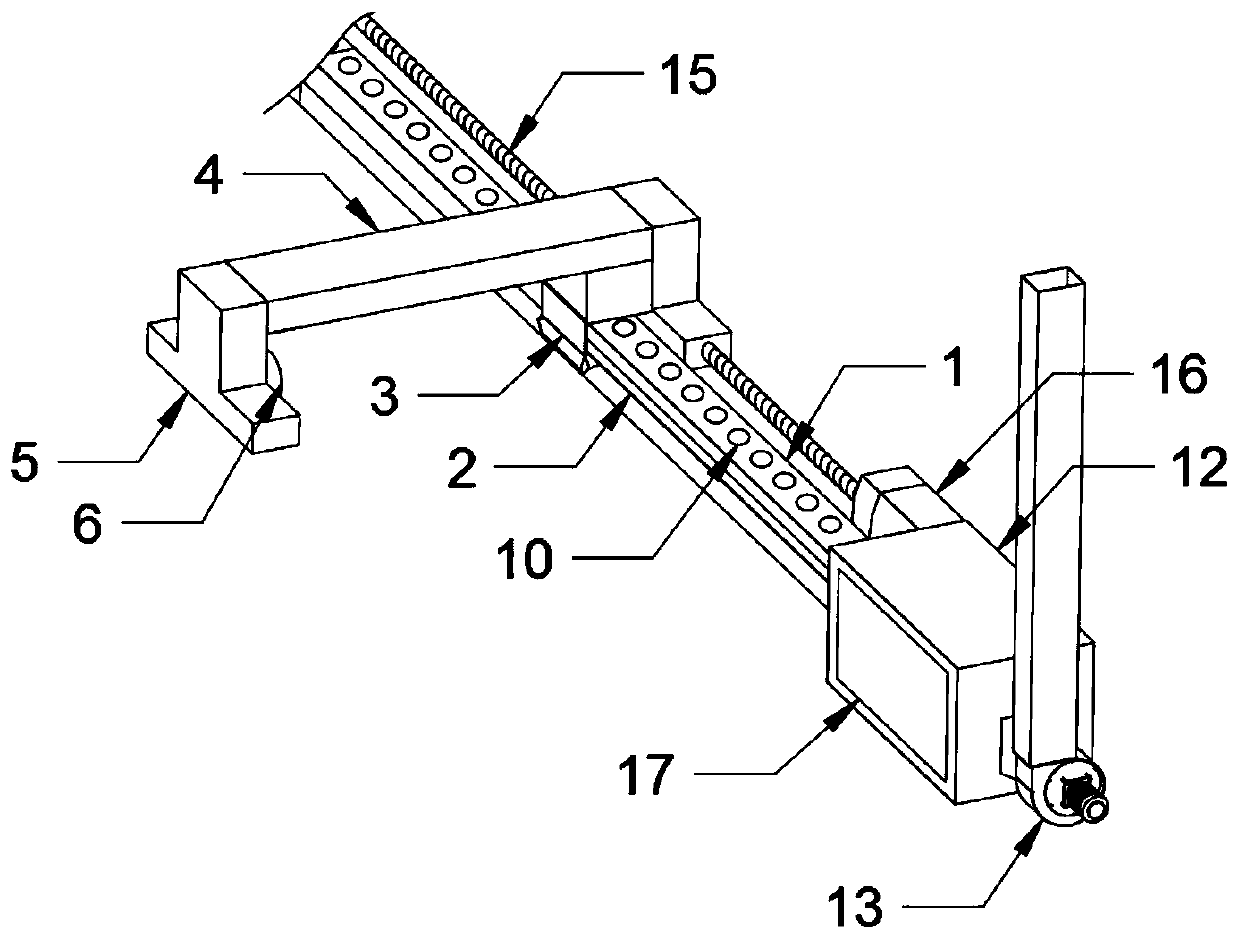
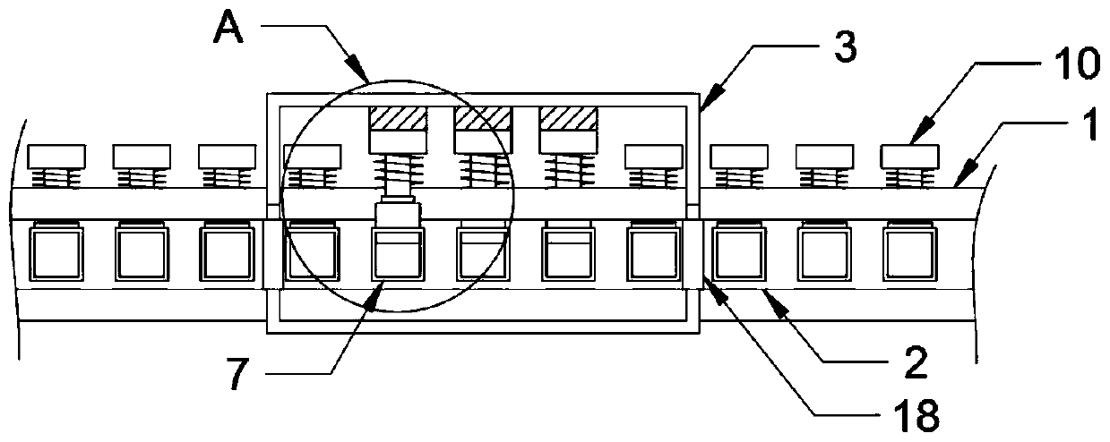
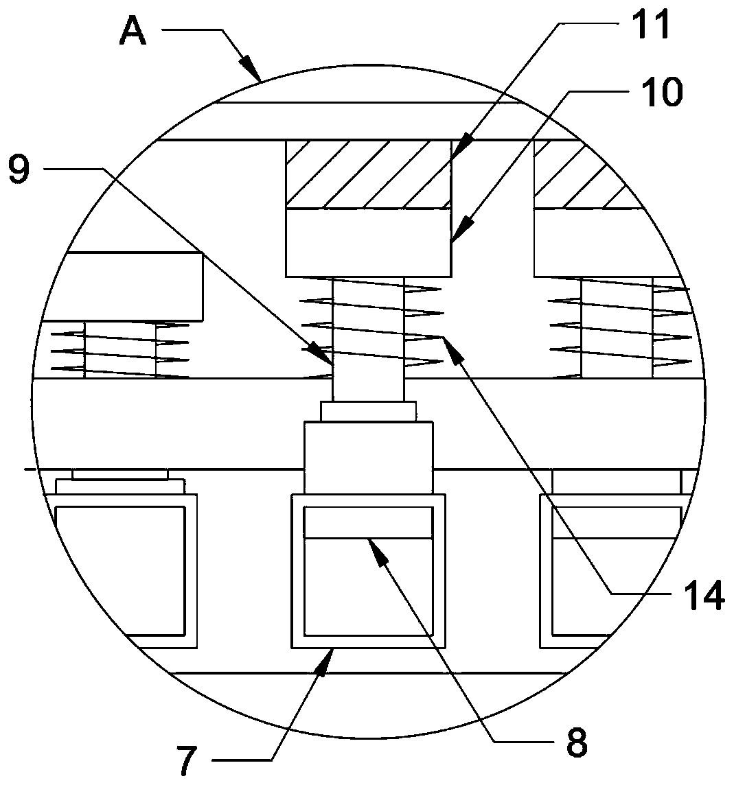
[0019] see Figure 1-3 , the present invention provides a technical solution: a slidable smoke exhaust system, including a slide rail 1, a slide groove 2 is provided on the lower surface of the slide rail 1, and a dust suction head is movable inside the slide groove 2 3. The upper end of the dust suction head 3 is fixedly provided with a connecting arm 4, and the lower end of the connecting arm 4 away from the slide rail 1 is fixedly provided with a CNC cuttin...


PUM


Abstract

The invention discloses a slidable smoke exhaust system. The slidable smoke exhaust system involves a sliding rail, wherein a sliding groove is formed in the surface of the lower end of the sliding rail, and a dust suction head is movably arranged inside the sliding groove in a clamped mode; a connecting arm is fixedly arranged at the upper end of the dust suction head, a numerical control cuttingmachine body is fixedly arranged at the lower end of the side, far away from the sliding rail, of the connecting arm, and an axial flow fan is fixedly arranged on one side of the surface of the numerical control cutting machine body through a mounting base; through grooves are formed in the surface of the sliding groove, baffles are arranged inside the through grooves in a clamped mode, connecting rods are fixedly arranged at the upper ends of the baffles, and first magnets are fixedly arranged at the upper ends of the connecting rods; and second magnets are evenly and fixedly arranged at theupper end of the interior of the dust suction head, and a cavity is fixedly formed in one end of the sliding rail. The slidable smoke exhaust system is simple in structure and good in use effect, canmove along with the numerical control cutting machine body, and sucks and purifies smoke dust discharged by the cutting machine body when a cutting machine works.

Description

technical field [0001] The invention relates to the technical field of smoke exhaust and dust suction, in particular to a slidable smoke exhaust system. Background technique [0002] The steel rolled from the steel mill is transported to the workshop. According to the design, these plates need to be cut and processed. CNC plasma and flame cutting equipment are used to cut and prepare materials. During the cutting process, due to the use of thermal processing, the steel plates are The impurities and molten iron will produce a large amount of harmful gases under the action of high temperature, causing air pollution in the workshop, and the ambient temperature of the workshop will rise, affecting the physical and mental health of workshop operators. [0003] Since the CNC cutting machine needs to move left and right to cut steel during work, there is currently a lack of convenient vacuum devices that can follow the CNC cutting machine to move left and right. The current vacuum ...

Claims


Application Information

Patent Timeline
IPC IPC(8): B23K7/10B23K10/00B08B15/00B01D46/00B01D53/04
CPCB01D46/0036B01D53/04B01D2258/0283B08B15/002B23K7/10B23K10/00
Inventor 仲辉
Owner QINGDAO WANCHENG ANCHOR CHAIN
Learn More