
Vacuum cleaner floor brush and vacuum cleaner with the vacuum cleaner floor brush

A technology of vacuum cleaner and rolling belt, which is applied in the field of vacuum cleaner with the floor brush of the vacuum cleaner, can solve the problems of cumbersome use process, affecting air fluidity, and difficulty in fully utilizing the vacuum degree, and achieve the effect of simplifying the structure

Inactive Publication Date: 2011-08-24
郑恬晨
View PDF0 Cites 0 Cited by
  • Summary
  • Abstract
  • Description
  • Claims
  • Application Information

AI Technical Summary

Problems solved by technology

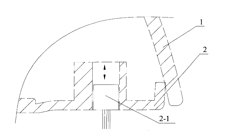
[0006] Although the floor brush of the vacuum cleaner provided by this prior art can be used on carpets and floors, the complexity of the structure of the floor brush of the vacuum cleaner is increased due to the need for a brush and a locking mechanism; The position of the hair brush 2-1 on the environment adjustment base plate 2
At the same time, when used on a carpet, it is difficult for the vacuum cleaner to inhale the dust attached to the deeper part of the carpet; in addition, the soft layer of the carpet will be more tightly squeezed by the bottom plate of the vacuum cleaner, which will affect the fluidity of the air. It is beneficial to thoroughly remove the dust attached to the deeper part of the carpet
[0007] In addition, in the prior art, since the bonding surface between the carpet or the floor and the base plate is relatively large, it is very easy to generate static electricity. In order to prevent static electricity from affecting the effect of dust collection, the existing vacuum cleaner should install corresponding static electricity on the bottom surface of the base plate 2. Strips to absorb the generated static electricity, which further increases the complexity of the brush structure of the vacuum cleaner
Moreover, the bonding surface between the carpet or the floor and the bottom plate is relatively large, and the suction port is located on both sides of the bottom plate. After entering the suction chamber, the air will directly flow into the main body of the vacuum cleaner. The air flow cannot completely bring the dust in the space inside the suction port into the vacuum cleaner. In the main body 300; some vacuum cleaners have a rotating brush in the suction port to raise the dust, but it is also difficult to improve the defect of small air inflow surface, which makes it difficult to fully utilize the vacuum degree generated by the motor drive of the vacuum cleaner, which affects the dust collection effect
[0008] In a word, the structure of the vacuum cleaner in the prior art, especially the structure of the ground brush of the vacuum cleaner needs to be further improved.

Method used


Image

  • Vacuum cleaner floor brush and vacuum cleaner with the vacuum cleaner floor brush
  • Vacuum cleaner floor brush and vacuum cleaner with the vacuum cleaner floor brush
  • Vacuum cleaner floor brush and vacuum cleaner with the vacuum cleaner floor brush

Examples


Embodiment Construction

[0048] The present invention will be described in detail below in conjunction with the accompanying drawings. The description in this part is only exemplary and explanatory, and should not have any limiting effect on the protection scope of the present invention.

[0049] combine Figure 4 to Figure 5 The floor brush of the vacuum cleaner provided by Embodiment 1 includes an upper cover 1, a bottom plate 2, a front rolling shaft 22, a rear rolling shaft 23, a left side plate 24 and a right side plate 25, and the upper cover 1 and the bottom plate 2 are fixed to form a Suction chamber 3.

[0050] give together Figure 5 and Figure 6 , the left side plate 24 and the right side plate 25 also include two side bearings 25-1, middle part 25-2, endless rolling belt 25-3 and needle roller 25-4 respectively, and the two side bearings 25 -1 axes are parallel or substantially parallel, and are installed on the base plate 2, and the middle part 25-2 is fixed to the base plate 2. In t...


PUM


Abstract

The invention discloses a dust collector floor-brush and a dust collector with the floor-brush. The dust collector floor-brush comprises an upper cover and a bottom plate, wherein the upper cover is mutually fixed on the bottom plate, also comprises a front rolling axle, a back rolling axle, a left side-plate and a right side-plate; the front rolling axle and the back rolling axle comprise middleholes and bosses are set on the circumference surfaces and a plurality of radial holes communicated with the boss surfaces are set on the bosses; and the boss surface of the front rolling axle is seton the first reference cylindrical surface and the boss surface of the back rolling axle is set on the second reference cylindrical surface and the rolling axles are rotatably mounted on the bottom plate; the left, right side-plates are fixed on the bottom plate and the inner end surfaces of the left, right side-plates respectively stick to the left, right end surfaces of the front, back rolling axles; the bottom of the left side-plate and the bottom of the right side-plate are in the same reference plane, and the reference plane is outside the bottom plate and tangent with the first reference cylindrical surface and the second reference cylindrical surface. The dust collector floor-brush has features of simpler structure, more convenient use, improved air flowing property, increased dustcollection effect of the dust collector.

Description

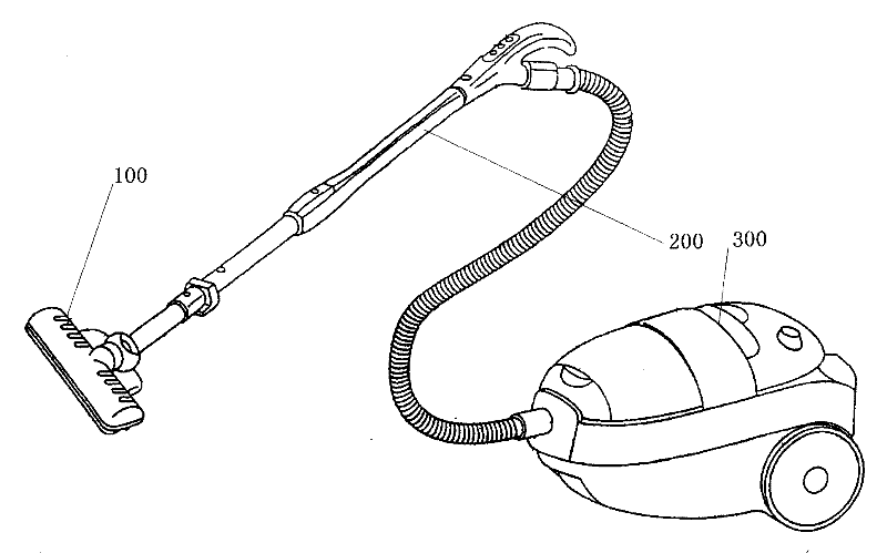
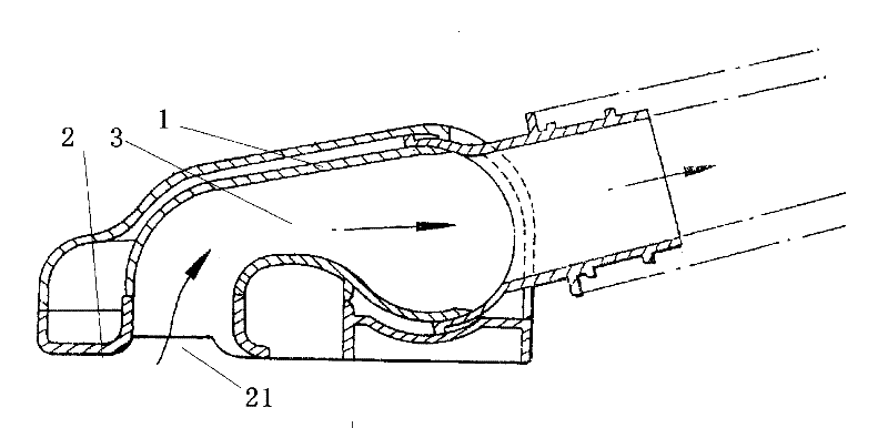
technical field [0001] The invention relates to a vacuum cleaner technology, in particular to a vacuum cleaner brush, and also to a vacuum cleaner with the vacuum cleaner brush. Background technique [0002] Currently, vacuum cleaners are an important tool for people to clean their living and working environments. The general working principle of the vacuum cleaner is that the impeller is driven by the motor to rotate, and a corresponding vacuum is formed at the suction port. External debris and air enter the suction chamber under the action of external air pressure; then the debris is filtered through the filter device, allowing the filter The exhausted air is discharged from the vacuum cleaner through the exhaust port, and the sundries and dust are left in the dust storage room. [0003] figure 1 It is a household vacuum cleaner, which includes a vacuum cleaner brush 100 , a connecting pipe 200 and a vacuum cleaner main body 300 . figure 2 It is a sectional view of the...

Claims


Application Information

Patent Timeline
Patent Type & Authority Patents(China)
IPC IPC(8): A47L9/02A47L5/12
Inventor 郑恬晨
Owner 郑恬晨
Learn More