Vision localization method of laser marking software

A technology of visual positioning and laser marking, which is applied in the field of visual positioning of laser marking software, and can solve the problems of cumbersome debugging positions and angles

Inactive Publication Date: 2020-04-24
深圳市诺亚云谷科技有限公司
View PDF7 Cites 4 Cited by
  • Summary
  • Abstract
  • Description
  • Claims
  • Application Information

AI Technical Summary

Problems solved by technology

However, it is necessary to make row and column fixtures according to d

Method used


Image

  • Vision localization method of laser marking software

Examples


Embodiment Construction

[0026] The following will clearly and completely describe the technical solutions in the embodiments of the present invention with reference to the accompanying drawings in the embodiments of the present invention. Obviously, the described embodiments are only some, not all, embodiments of the present invention. Based on the embodiments of the present invention, all other embodiments obtained by persons of ordinary skill in the art without creative efforts fall within the protection scope of the present invention.

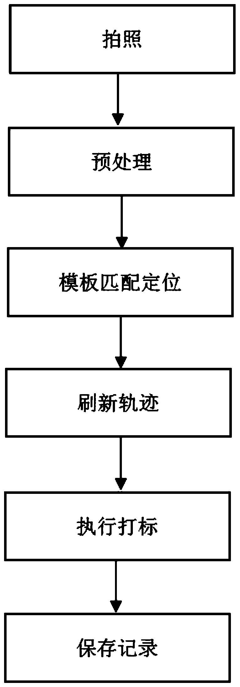
[0027] A visual positioning method for laser marking software, comprising the following steps:

[0028] Step 1. Arbitrarily place the product in the working range of the marking table, take pictures with the camera to obtain the product picture, and load the template parameters in the software;

[0029] Step 2. Preprocessing the product image according to the template parameters to obtain the preprocessed image;

[0030] Step 3. Traverse the picture, and find the ...


PUM


Abstract

The invention discloses a vision localization method of laser marking software. The method comprises the following steps that S1, a product is placed within the work range of a marking table freely, acamera takes a picture to obtain a product picture, and the software loads template parameters; S2, according to the template parameters, the product picture is preprocessed to obtain a preprocessedpicture; S3, traversal of the picture is carried out, and through the template parameters, area coordinates the same with a template are found out and that is a product center; and S4, a template picture is used again, an area is subjected to characteristic point and gray matching and outline fitting, an angle is obtained, and visual treatment is finished. Different clamps do not need to be manufactured according to products, red light preview is not needed, product image template parameters are edited in advance, subsequent any placement is achieved, a visual system automatically finds a target position and direction, deviation is corrected automatically, and precise marking is achieved.

Description

Technical field: [0001] The invention relates to the technical field of laser marking, in particular to a visual positioning method of laser marking software. Background technique: [0002] Laser marking technology is one of the largest application areas of laser processing. Laser marking is a marking method that uses a high-energy-density laser to locally irradiate the workpiece to vaporize the surface material or undergo a chemical reaction of color change, thereby leaving a permanent mark. Laser marking can print various characters, symbols and patterns, etc., and the character size can range from millimeters to microns, which has special significance for product anti-counterfeiting. [0003] In the traditional laser marking technology, the user makes standard jigs and fixes the jigs to the fixed position of the marking machine. According to the width of the row and column of the fixture, program in the software. Use the red light preview to determine if the position i...

Claims


Application Information

Patent Timeline
IPC IPC(8): B23K26/362B23K26/70
CPCB23K26/362B23K26/702
Inventor 杨长春邓云涛文信富莫赞
Owner 深圳市诺亚云谷科技有限公司
Why Eureka
Try Eureka