Microprism die manufacturing method reducing joint dark band

A technology of patchwork dark zone and production method, which is applied in the direction of manufacturing tools, welding equipment, laser welding equipment, etc., can solve the problems of reducing mold patchwork dark zone, large invalid reflective area, etc., to reduce the width of non-reflective dark zone, Wide range of application and the effect of reducing the width of dark bands

Active Publication Date: 2020-04-24
福建跃发光新材料股份有限公司
View PDF5 Cites 4 Cited by
  • Summary
  • Abstract
  • Description
  • Claims
  • Application Information

AI Technical Summary

Problems solved by technology

[0011] The embodiment of the present application provides a method for making a microprism mold that reduces the dark band of the seam, which solves the problem in the prior art of cutting the mold sheet with rough machining technology, resulting in a large invalid reflection area, and realizes the reduction of the mold. Patchwork dark bands, and then reduce the width of the non-reflective dark bands of the reflective original film formed after the optical film is planted, and improve the overall reflective efficiency of the microprism reflective film

Method used


Image

  • Microprism die manufacturing method reducing joint dark band
  • Microprism die manufacturing method reducing joint dark band
  • Microprism die manufacturing method reducing joint dark band

Examples


Embodiment 1

[0050] A method for making a microprism mold that reduces the dark band of the seam, comprising the steps of:

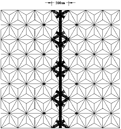
[0051] (1) see Image 6 , select a microprism initial template 5, and place it under a microscope, adjust the magnification of the microscope until the microprism initial template 5 can be clearly observed, observe the direction of the microprism initial template 5 pyramid arrays and the fine V grooves of the microprism In the direction, mark the direction and distance m of the tool machining path, and measure the thickness d of the initial template 5 of the microprism to be processed (d refers to the distance from the bottom of the micro V groove to the non-pyramid surface), and measure the micro V groove Groove angle a.

[0052] (2) Select the tool used for finishing cutting. The tool is a V-shaped knife with a V-shaped cross section, and install the tool on the cutting path running device.

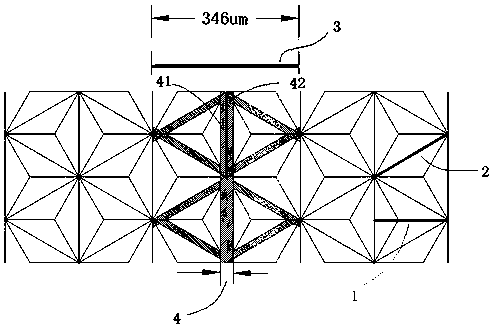
[0053] (3) see Figure 5 , the microprism initial template 5 to be pro...

Embodiment 2

[0060] A method for making a microprism mold that reduces the dark band of the seam, comprising the steps of:

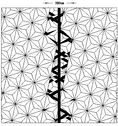
[0061] (1) Select an initial microprism template 5, place it under a microscope, adjust the magnification of the microscope until the initial microprism template 5 can be clearly observed, observe the direction of the pyramid array of the initial microprism template 5 and the microprism fine V The direction of the groove, mark the direction and distance m of the tool machining path, and measure the thickness d of the initial template 5 of the microprism to be processed (d refers to the distance from the bottom of the micro-V groove to the non-pyramid surface), and measure the micro-prism V-groove angle a, unit pyramid size 1, unit pyramid ineffective reflective area size L1, see Figure 11 shown.

[0062] (2) Select the tool used for finishing cutting. The tool is a V-shaped knife with a V-shaped cross section and is installed on the cutting path running device.

...


PUM


Abstract

The invention discloses a microprism die manufacturing method reducing a joint dark band and particularly relates to finish machining modes. Through ultraprecise cutting equipment, die pieces or die strips are obtained through cutting by a V-shaped triangular cutter along micro-thin V-shaped groove paths of an existing pyramid-array microprism initial die and are used for manufacturing various specifications of working dies of shadow stripes, squares and the like. A cutting method is provided, unit microprism pyramid integrity is kept, unit microprism effective reflective area integrity is kept to the greatest extent, the width of the non-reflective joint dark band of the working die is reduced, the overall reflective efficiency of the working die is improved effectively, and then microprism reflective films high in reflective efficiency, high in integrity and high in consistency and of shadow stripes, squares and other various appearances are produced.

Description

technical field [0001] The invention relates to the field of optical mold manufacturing, in particular to a method for manufacturing a microprism mold that reduces dark bands in seams. Background technique [0002] The non-reflective principle of the apex and corner points of the complete unit pyramid: the light is irradiated on one of the sides of the concave pyramid, and the three sides of the three nanometer-level smoothness inside the concave pyramid produce total reflection, and are reflected three times Go back along the original path, but when the light shines on the lowest point of the concave pyramid, that is, near the apex of the convex pyramid, since the three sides converge into a point here, the space near the concave point is narrow, and the light is reflected in an infinite loop in this space, so The reflected light is bound here, and there is no way to reflect back to the light source, resulting in a reflective invalid area; and near the corner of the concave...

Claims


Application Information

Patent Timeline
Patent Type & Authority Applications(China)
IPC IPC(8): B23P15/24B23K26/24
CPCB23K26/24B23P15/24
Inventor 梁桂德许明旗黄志鹏黄志江朱庆强蔡佳旺
Owner 福建跃发光新材料股份有限公司
Why Eureka
Try Eureka