Inspection robot

A technology for inspection robots and fuselages, applied in the field of inspection robots, can solve the problems that inspection robots cannot flexibly adapt to different inspection tasks

Active Publication Date: 2021-12-07
UBTECH ROBOTICS CORP LTD
View PDF8 Cites 6 Cited by
  • Summary
  • Abstract
  • Description
  • Claims
  • Application Information

AI Technical Summary

Problems solved by technology

[0003] The purpose of this application is to provide an inspection robot, which aims to solve the problem in the prior art that the inspection robot cannot flexibly adapt to different inspection tasks

Method used


Image

  • Inspection robot
  • Inspection robot
  • Inspection robot

Examples


specific Embodiment approach

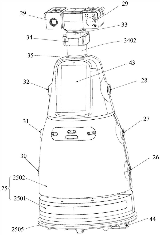
[0046] Further, as another specific implementation of the inspection robot provided in this application, it also includes modules such as PM2.5 (fine particulate matter) detection, temperature and humidity detection, and RFID (radio frequency identification) to detect multiple types of data , and display and operate through the above-mentioned touch screen 43 .

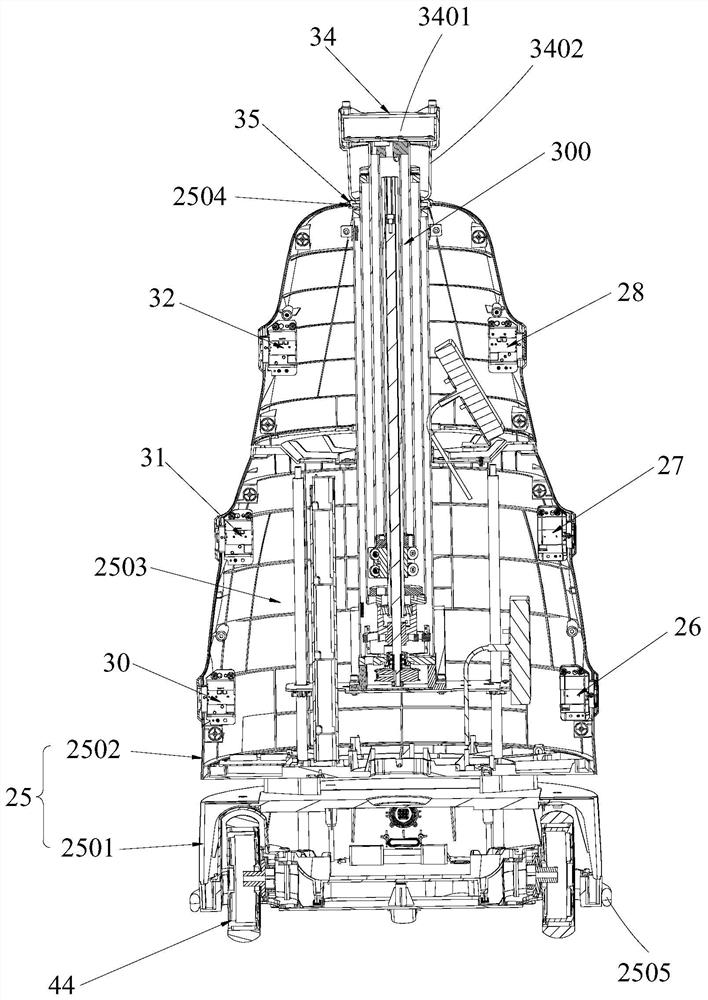
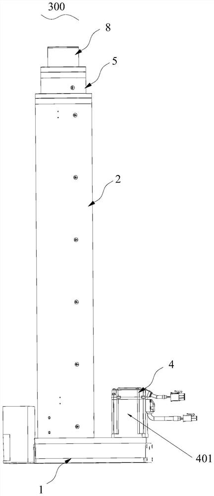
[0047] Further, see Figure 1-Figure 2 , as another specific embodiment of the inspection robot provided by the present application, a fixed frame 34 is provided between the lifting mechanism 300 and the cloud platform 33; the cloud platform 33 is connected to the output end of the lifting mechanism 300 through the fixed frame 34; the fixed frame 34 is provided with accommodating groove 3401; Cloud platform 33 is inserted in the containing groove 3401, can realize the fast installation of cloud platform 33; The barrel 3402 is sheathed on the outside of the lifting mechanism 300 , so that foreign matter from the outsi...


PUM


Abstract

The application discloses an inspection robot, which includes a fuselage, a lifting mechanism arranged on the fuselage, a pan-tilt installed on the movable end of the lifting mechanism, an inspection camera unit rotatably mounted on the pan-tilt, and an inspection camera unit installed on the bottom of the fuselage. The mobile wheel set; the platform has a first drive assembly for driving the inspection camera unit to deflect. The lifting mechanism can move the inspection camera unit within a certain height range to meet the collection of image information of cabinets of different heights, thereby meeting the requirements of different inspection tasks for image acquisition, and then implementing different inspections flexibly according to requirements. check task.

Description

technical field [0001] The present application relates to the field of inspection equipment, in particular to an inspection robot. Background technique [0002] At present, the computer room inspection in the industry mainly relies on manual inspection, which is inefficient and error-prone. For some computer room environments with poor conditions, the working environment for personnel is very difficult. The existing inspection method is to install a camera on a hanging rail. The camera moves on a fixed track, and the trajectory of the movement is also certain, and the inspection path is also relatively fixed, which cannot be flexibly adapted to different inspection tasks. At the same time, this type of equipment requires a large transformation of the machine room, and the installation cost is relatively high. Contents of the invention [0003] The purpose of the present application is to provide an inspection robot, aiming to solve the problem in the prior art that the i...

Claims


Application Information

Patent Timeline
Patent Type & Authority Patents(China)
IPC IPC(8): B25J5/00B25J11/00B25J19/02H04N5/225H04N5/247
CPCB25J5/007B25J11/00B25J19/023H04N23/57H04N23/90
Inventor 周礼兵陆桂松赵娜余文华熊友军
Owner UBTECH ROBOTICS CORP LTD
Why Eureka
Try Eureka