Self-dedusting road reflector

A self-dusting and reflecting mirror technology, applied in the field of municipal engineering, can solve problems such as increased labor costs, scratches on the mirror surface, and the device cannot properly remove dust, and achieves the effect of sufficient dust removal and low manufacturing cost.

Inactive Publication Date: 2020-04-24
杨程聆
View PDF9 Cites 10 Cited by
  • Summary
  • Abstract
  • Description
  • Claims
  • Application Information

AI Technical Summary

Problems solved by technology

[0006] First, the wiper device in the above solution is arranged on the mirror surface, so when the wiper device rotates to scrub the mirror surface, the mirror surface will be scratched by the wiper, and scratches will appear on the mirror surface, causing the driver to be unable to see clearly the scene in the mirror surface. picture;
[0007] Second, the above schemes use more precision electronic components such as rain sensors, timers and controllers. However, since road reflectors are mostly installed outdoors, they will inevitably be exposed to wind and sun. In this environment, Various electronic components are prone to failure, resulting in the failure of the entire device to remove dust normally. At the same time, these electronic components require regular maintenance by special personnel, which greatly increases labor costs

Method used


Image

  • Self-dedusting road reflector
  • Self-dedusting road reflector
  • Self-dedusting road reflector

Examples


Embodiment 1

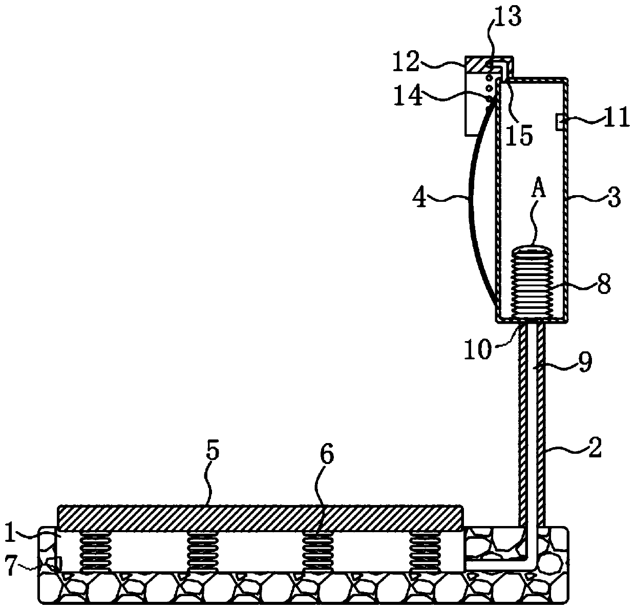
[0028] Reference Figure 1-2 , A self-cleaning road reflector, comprising a chute 1 opened on the ground and a housing 3 fixedly connected to the ground by a support rod 2. A speed bump 5 is sealed and slidingly connected to the chute 1, and the side wall of the housing 3 is fixed A mirror 4 is installed, the upper end of the housing 3 is fixedly connected with an arc-shaped rain shield 12, and the deceleration belt 5 is elastically connected to the inner bottom of the chute 1 through multiple sets of first springs 6, and an air inlet 7 is provided on the inner wall of the chute 1 , The inner wall of the housing 3 is fixedly connected with a telescopic airbag 8, the lower end of the chute 1 communicates with the telescopic airbag 8 through the air guide cavity 9, and the connection between the air guide cavity 9 and the telescopic airbag 8 is installed with a device that only allows air to flow from bottom to top The first one-way valve 10.

[0029] The air inlet 7 is connected t...

Embodiment 2

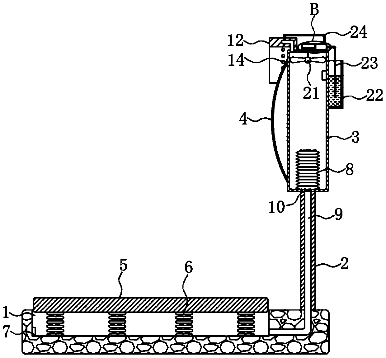
[0038] Reference Figure 3-4 The difference from Embodiment 1 is that the inner top of the housing 3 is rotatably connected with an impeller 21 through a rotating shaft, a water tank 22 with an opening at the upper end is fixedly connected to the side wall of the housing 3, and a device box 30 is fixedly connected to the upper end of the housing 3 A cleaning mechanism for cleaning the mirror 4 is installed in the device box 30, and a driving mechanism for driving the cleaning mechanism is also installed in the device box.

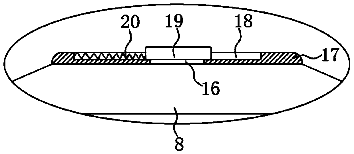
[0039] The cleaning mechanism includes a sliding plug 27 sealed and slidingly connected to the device box 30. The end of the device box 30 is in communication with the water tank 22 through a water inlet pipe 23, and the water inlet end of the water inlet pipe 23 is submerged below the liquid level in the water tank 22, and the water inlet pipe 23 A third check valve 29 that only allows air to flow from the water inlet pipe 23 to the device box 30 is installed...


PUM


Abstract

The invention discloses a self-dedusting road reflector. The reflector comprises a chute arranged on the ground and a shell fixedly connected to the ground through a supporting rod. A deceleration strip is connected into the chute in a sealed and sliding mode, a mirror surface and an arc-shaped flashing board are fixedly installed on the side wall and the upper end of the shell respectively, the deceleration strip is elastically connected to the inner bottom of the chute through a plurality of sets of first springs, an air inlet is formed in the inner wall of the chute, and a telescopic air bag is fixedly connected into the shell. An exhaust mechanism, an telescopic air bag, an impeller, a driving mechanism and a cleaning mechanism are arranged, air can be pumped into the telescopic air bag, air is stored, the stored air is used for removing dust on the mirror surface, the impeller can be driven to rotate through the sprayed air, then the cleaning mechanism pumps water to clean the mirror surface, dust on the mirror surface is thoroughly removed, manual cleaning is not needed, the mirror surface is not damaged, the structure is simple, electronic components needing to be maintainedare not needed, and the cost is low.

Description

Technical field [0001] The invention relates to the technical field of municipal engineering, in particular to a self-dust removal type road reflector. Background technique [0002] Due to the limitation of the field of view, it is easy to form a blind angle at the corner of the road, and it is not easy for the driver to find the vehicles on the opposite side of the curve when passing by. Therefore, road reflectors are usually installed at the corner of the curve to use optical principles to enlarge Driver’s vision reduces the probability of accidents. [0003] However, because the road is already in the dusty area, and the vehicle will raise a lot of dust when driving, it is easy to stick more dust on the mirror surface of the road reflector set at the corner of the road. If the dust is not If you clean up in time, it will greatly hinder the driver's observation of the oncoming traffic, thereby increasing the probability of accidents. However, because of the fact that the reflect...

Claims


Application Information

Patent Timeline
Patent Type & Authority Applications(China)
IPC IPC(8): E01F9/619E01F9/529
CPCE01F9/529E01F9/619
Inventor 杨程聆胡建
Owner 杨程聆
Why Eureka
Try Eureka