Construction method and structure for partially replacing row pile support based on cutter suction type diaphragm wall

A ground-to-wall and twist-suction technology, which is applied in foundation structure engineering, excavation, sheet pile walls, etc., can solve problems such as the inability to close the foundation pit, the inability to relocate the pipeline, and the large diameter or width of the pipeline, so as to broaden the design ideas , high economic and social benefits, and wide application prospects

Pending Publication Date: 2020-04-24
CHINA RAILWAY FIRST SURVEY & DESIGN INST GRP
View PDF0 Cites 6 Cited by
  • Summary
  • Abstract
  • Description
  • Claims
  • Application Information

AI Technical Summary

Problems solved by technology

[0002] Subway construction is often carried out on busy roads in the city, and there are many surrounding pipelines. Most of the pipelines can be temporarily or permanently relocated outside the influence area of ​​the subway construction, but some important pipelines often cannot be relocated (such as 220KV power pipe trenches), and the diameter of the pipeline is The width is relatively large. In this case, the ordinary pile forming hole or ground-to-wall trough forming equipment encounters pipelines that cannot be relocated, resulting in the failure to close the foundation pit

Method used


Image

  • Construction method and structure for partially replacing row pile support based on cutter suction type diaphragm wall
  • Construction method and structure for partially replacing row pile support based on cutter suction type diaphragm wall
  • Construction method and structure for partially replacing row pile support based on cutter suction type diaphragm wall

Examples


Embodiment Construction

[0029] The present invention will be described in detail below in combination with specific embodiments.

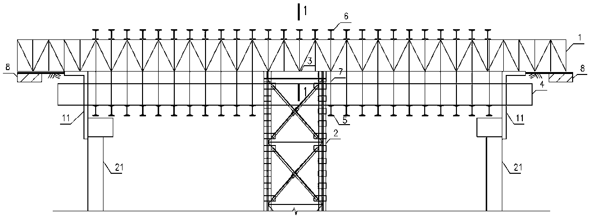
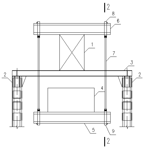
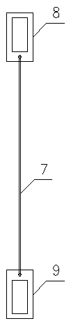
[0030] The invention relates to a construction structure based on a twisted-suction ground connection wall partially replacing row pile support, including a pipeline suspension protection structure and a steel cage outside the pipeline. The pipeline suspension protection structure includes lattice columns 2 on both lateral sides of the pipeline 4, a horizontal I-shaped steel platform 3 is arranged on the top of the lattice column 2, a vertical steel truss 1 is arranged above the I-shaped steel platform 3, and a vertical steel truss 1 is arranged above the steel truss 1. The upper I-beams 6 arranged in parallel in the longitudinal direction are arranged, and the lower I-beams 5 located under the pipeline 4 are suspended on both lateral sides of the upper I-beams 6 through the upper hanging parts 8, the upper chains 7 and the lower hanging parts 9. 4 is located above the lo...


PUM


Abstract

The invention relates to a construction method and structure for partially replacing a row pile support based on a cutter suction type diaphragm wall. The structure comprises a pipeline suspension protection structure and a pipeline outer reinforcement cage. The pipeline suspension protection structure comprises latticed columns on the two transverse sides of a pipeline, a transverse I-shaped steel platform is arranged at the tops of the latticed columns, longitudinal steel trusses are arranged above the I-shaped steel platform, upper I-shaped steel arranged in parallel in the longitudinal direction is arranged above the steel trusses, and lower I-shaped steel located below the pipeline is suspended on the two transverse sides of the upper I-shaped steel through chain blocks. The pipelineis located above the lower I-shaped steel. According to the construction method and structure, the row pile support is partially replaced, the pipeline is suspended through the steel trusses, gas-liftreverse circulation grooving is carried out through a submersible drill, the reinforcement cage is machined in two sections and then is in butt joint in a male-female mode, concrete is poured to forma wall, and therefore the purpose that a foundation pit at the position wherein the pipeline cannot be moved and changed in an urban flourishing road section can be normally closed is achieved.

Description

technical field [0001] The invention belongs to the technical field of foundation pit engineering, and in particular relates to a construction method and structure based on a twisted suction type ground connection wall partially replacing row pile support. Background technique [0002] Subway construction is often carried out on busy roads in the city, and there are many surrounding pipelines. Most of the pipelines can be temporarily or permanently relocated outside the influence area of ​​the subway construction, but some important pipelines often cannot be relocated (such as 220KV power pipe trenches), and the diameter of the pipeline is The width is relatively large. In this case, ordinary pile-forming holes or ground-to-wall trenching equipment encounter pipelines that cannot be relocated, resulting in the failure to close the foundation pit. Contents of the invention [0003] The purpose of the present invention is to provide a construction method and structure based ...

Claims


Application Information

Patent Timeline
Patent Type & Authority Applications(China)
IPC IPC(8): E02D17/04E02D5/18
CPCE02D5/187E02D17/04
Inventor 王立新夏宏运许昭魏庆繁高志宏汪珂
Owner CHINA RAILWAY FIRST SURVEY & DESIGN INST GRP
Why Eureka
Try Eureka