Water inflow control device with time delay function

A technology of water inlet control and function, applied in water supply devices, flushing equipment with water tanks, buildings, etc., can solve the problems of water inlet valve not stopping, rising high, and small floating bucket floating in advance, so as to prevent more water , the structure is simple, the water level rises steadily

Pending Publication Date: 2020-04-24
XIAMEN R&T PLUMBING TECH
View PDF0 Cites 1 Cited by
  • Summary
  • Abstract
  • Description
  • Claims
  • Application Information

AI Technical Summary

Problems solved by technology

[0002] In the prior art, a water inlet valve and a water inlet control device are installed in the toilet water tank. The water inlet valve supplies water to the water tank or supplies water to the outside of the water tank under the action of the water inlet control device. The water inlet control device usually includes a control unit and a stop. The water unit also includes a first water outlet channel for water supply to the toilet tank, the water stop unit is used to control the opening and closing of the first water outlet channel, the control unit includes a small water tank connected with the toilet tank and a small The floating barrel drives the water stop unit to control the opening and closing of the first water outlet channel. However, when the flow rate of water entering the small water tank is too fast or the water pressure is too high, the water level in the small water tank will rise higher, and the small floating barrel will Floating ahead of time, the first water outlet channel is closed in advance, that is, the water level of the water tank cannot reach the water stop level, and the water in the water inlet valve has been flowing to the outside of the water tank, causing the water inlet valve to not stop

Method used


Image

  • Water inflow control device with time delay function
  • Water inflow control device with time delay function
  • Water inflow control device with time delay function

Examples


Embodiment 1

[0042] Embodiment 1: (movable part 24 cooperates with the opening and closing of water passage 22)

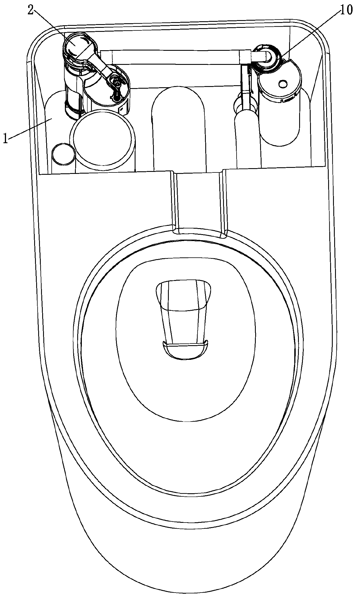
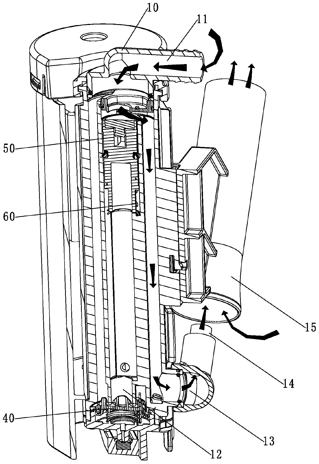
[0043] Such as Figure 1 to Figure 5 As shown, a water inflow control device with a delay function, including:

[0044] The water inlet channel 11 communicates with the water outlet channel of the water inlet valve 2;

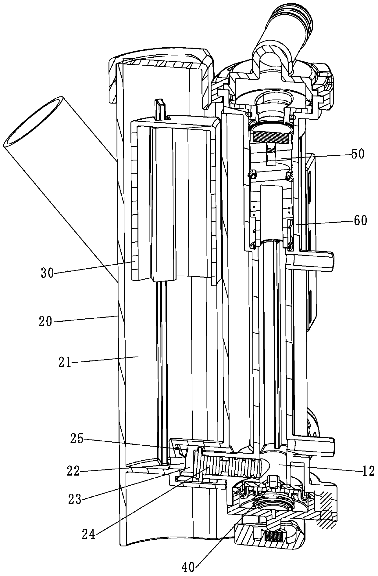
[0045] The first water outlet channel 12 communicates with the water inlet channel 11 and can supply water to the toilet tank 1;

[0046] The small water tank 20 has a water storage chamber 21 and a water passage 22 connecting the water storage chamber 21 with the toilet tank;

[0047] The water stop unit includes a small floating bucket 30, which floats or falls with the water level in the water storage chamber 21 to control the opening and closing of the first water outlet channel 12;

[0048] A control unit, when the water inlet channel 11 is filled with water and the first water outlet channel 12 is opened, the control unit controls the small floating bucke...

Embodiment 2

[0062] Embodiment 2: (the movable part 24 and the small buoy 30 limit or give way to cooperate)

[0063] Such as Image 6 with Figure 7 As shown, the main difference between this embodiment and the above-mentioned embodiments is that in this embodiment, the movable part 24' and the small floating bucket 30' are limited or given way. When the movable part 24' moves to the At the first position, the movable part 24' limits the small floating bucket 30' at the falling position, and when the movable part 24' moves to the second position, the movable part 24' Release the limit on the small floating bucket 30', specifically, the small floating bucket 30' has a connecting arm 31' extending downward, the movable part 24' has a rib 241' extending outward, and the movable part 24 When moving to the first position, the rib 241' of the movable part 24' abuts against the connecting arm 31' to limit the position.

[0064] Other parts not described are consistent with the above-mentioned...


PUM


Abstract

The invention discloses a water inflow control device with a time delay function. The device comprises: a first water outlet channel, which is communicated with a water inlet channel and can control water supply to a closestool water tank; a small water tank, which is equipped with a water storage cavity and a water channel that communicates the water storage cavity with the closestool water tank;a water stop unit, which comprises a small floating barrel that floats up or falls down along with the water level in the water storage cavity so as to control opening and closing of the first wateroutlet channel; a control unit, which controls the small floating barrel for keeping in a falling state under the action of water pressure of the first water outlet channel when water enters the waterinlet channel and the first water outlet channel is opened, thus keeping the first water outlet channel open, and which resets after the water inlet channel stops water so that the small floating barrel floats upwards along with the water level in the water storage cavity to close the first water outlet channel. According to the scheme, the control unit is disposed to enable delayed floating of the small floating barrel, the water inflow control device can have sufficient water supply time for the closestool water tank, the water level of the closestool water tank stably rises, the problem that the water inflow control device does not stop water is prevented, and the structure is simple.

Description

technical field [0001] The invention relates to a water inflow control device with a delay function. Background technique [0002] In the prior art, a water inlet valve and a water inlet control device are installed in the toilet water tank. The water inlet valve supplies water to the water tank or supplies water to the outside of the water tank under the action of the water inlet control device. The water inlet control device usually includes a control unit and a stop. The water unit also includes a first water outlet channel for water supply to the toilet tank, and the water stop unit is used to control the opening and closing of the first water outlet channel. The control unit includes a small water tank connected with the toilet tank and a small The floating barrel drives the water stop unit to control the opening and closing of the first water outlet channel. However, when the flow rate of water entering the small water tank is too fast or the water pressure is too high...

Claims


Application Information

Patent Timeline
Patent Type & Authority Applications(China)
IPC IPC(8): E03D1/32E03D1/33
CPCE03D1/302E03D1/32E03D1/33
Inventor 黄贵阳潘东东钟志军
Owner XIAMEN R&T PLUMBING TECH
Why Eureka
Try Eureka