A clockless chip wake-up circuit, wake-up method, and chip

A wake-up circuit, clockless technology, applied in the direction of electrical digital data processing, instruments, calculations, etc., can solve the problem of extra power consumption of the clock, achieve low power consumption and improve circuit reliability

Active Publication Date: 2021-05-25
GREE ELECTRIC APPLIANCES INC
View PDF13 Cites 0 Cited by
  • Summary
  • Abstract
  • Description
  • Claims
  • Application Information

AI Technical Summary

Problems solved by technology

[0005] The purpose of the present invention is to overcome the technical problem that the use of clock detection in the prior art will increase additional power consumption, and provide a clockless chip wake-up circuit, wake-up method, chip

Method used


Image

  • A clockless chip wake-up circuit, wake-up method, and chip

Examples


Embodiment Construction

[0028] The technical solutions in the present invention will be clearly and completely described below in conjunction with the accompanying drawings in the embodiments of the present invention. Obviously, the described embodiments are only part of the embodiments of the present invention, not all of them.

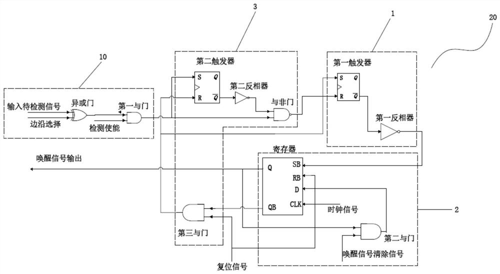
[0029] Such as figure 1 As shown, a clockless chip wake-up circuit includes an acquisition circuit 10 and a detection circuit 11, and the acquisition circuit 10 acquires an input signal to be detected; the acquisition circuit 10 includes an XOR gate and a first AND gate, and the XOR gate The first input terminal is connected to the signal to be detected, the second input terminal is connected to the edge selection signal, the output terminal is connected to the first input terminal of the first AND gate, and the second input terminal of the first AND gate is connected to the detection enable signal, The detection circuit 11 detects the signal to be detected, and generates a...


PUM


Abstract

The invention discloses a clockless chip wake-up circuit, a wake-up method, and a chip, including an acquisition circuit and a detection circuit. The acquisition circuit is used to collect input signals to be detected; the detection circuit is used to detect signals to be detected, and generate wake-up according to the signals to be detected. signal, the detection circuit includes a state detection module, a state latch module, and a state recovery module. The state detection module is connected to the acquisition circuit to detect whether there is a signal input to be detected. If there is a signal input to be detected, the state detection module outputs the signal to be detected. The latch module is connected with the state detection module, and generates a wake-up signal according to the signal to be detected. After the wake-up signal is generated, the state recovery module resets the state latch module and the state detection module, and returns to the detection state. By collecting the input signal to be detected, detecting the signal to be detected, and generating a wake-up signal according to the signal to be detected, clockless IO wake-up is realized, power consumption is minimized as much as possible, and circuit reliability is improved.

Description

technical field [0001] The invention relates to the field of electronic circuits, in particular to a clockless chip wake-up circuit, a wake-up method, and a chip. Background technique [0002] The microcontroller chip (MCU) has an independent processor, I / O device and memory, which can reduce the size and reduce the cost of equipment. It is widely used in various fields, such as household appliances, medical equipment, industrial control, remote equipment, office equipment, toys and embedded systems. [0003] Power consumption is a very important parameter to measure the microcontroller chip (MCU). For different chips that realize the same function, the higher power consumption density will cause the temperature of the chip to rise, affect the reliability of the circuit, and reduce the life of the device. High power consumption means more battery consumption and higher usage cost. Therefore, designing chips with low power consumption has become the mainstream demand of chip...

Claims


Application Information

Patent Timeline
Patent Type & Authority Patents(China)
IPC IPC(8): G06F1/3287G06F1/24
CPCG06F1/24G06F1/3287
Inventor 卢知伯陈恒张浩亮方励
Owner GREE ELECTRIC APPLIANCES INC
Why Eureka
Try Eureka