
Rail-mounted inspection robot charging device and working method thereof

A technology for inspection robots and charging devices, applied in circuit devices, battery circuit devices, coupling devices, etc., can solve problems such as falling off of charging contacts, poor contact, and inability to perform robot inspection tasks, achieving safe and stable charging, preventing shedding effect

Pending Publication Date: 2020-04-24
SHENZHEN SUNWIN INTELLIGENT CO LTD
View PDF0 Cites 3 Cited by
  • Summary
  • Abstract
  • Description
  • Claims
  • Application Information

AI Technical Summary

Problems solved by technology

[0003] For the track-type inspection robot, the device is the energy source of the machine. There are generally many cabinets in the power distribution room, and there are many information to be recorded on a single cabinet, so the inspection task of a single power distribution room is very large. Large, if the safe and stable charging process cannot be guaranteed, the robot inspection task cannot be carried out, thus losing the meaning of machine instead of manual inspection
At present, the charging method of orbital inspection robots on the market mostly adopts a single contact charging method, which may easily cause problems such as poor contact during charging, and easily cause the charging contacts to fall off, thereby affecting the charging quality.

Method used


Image

  • Rail-mounted inspection robot charging device and working method thereof
  • Rail-mounted inspection robot charging device and working method thereof
  • Rail-mounted inspection robot charging device and working method thereof

Examples


Embodiment Construction

[0026] In order to make the purpose, technical solution and advantages of the present invention clearer, the present invention will be further described in detail below in conjunction with the accompanying drawings and specific embodiments.

[0027] The following will clearly and completely describe the technical solutions in the embodiments of the present invention with reference to the accompanying drawings in the embodiments of the present invention. Obviously, the described embodiments are only some, not all, embodiments of the present invention. Based on the embodiments of the present invention, all other embodiments obtained by those skilled in the art without creative efforts fall within the protection scope of the present invention.

[0028] In describing the present invention, it should be understood that the terms "center", "longitudinal", "transverse", "length", "width", "thickness", "upper", "lower", "front", " Orientation or position indicated by "back", "left", "...


PUM


Abstract

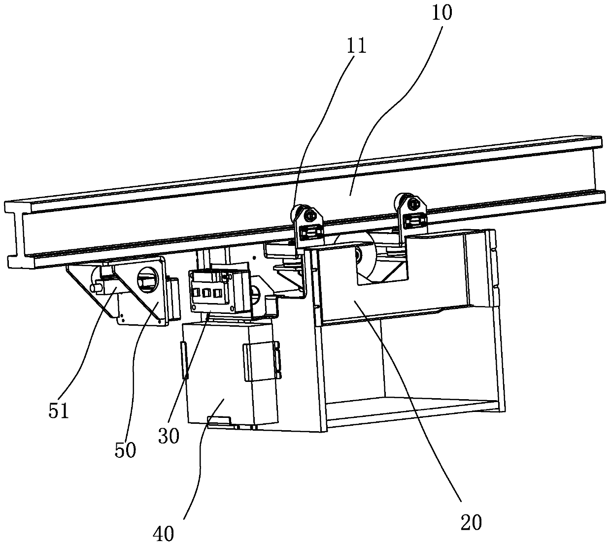
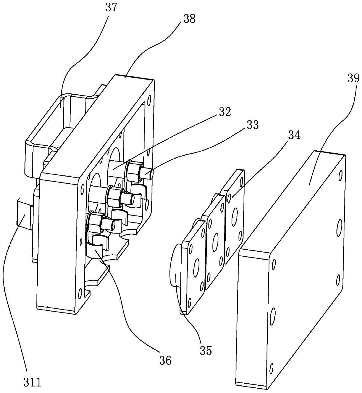
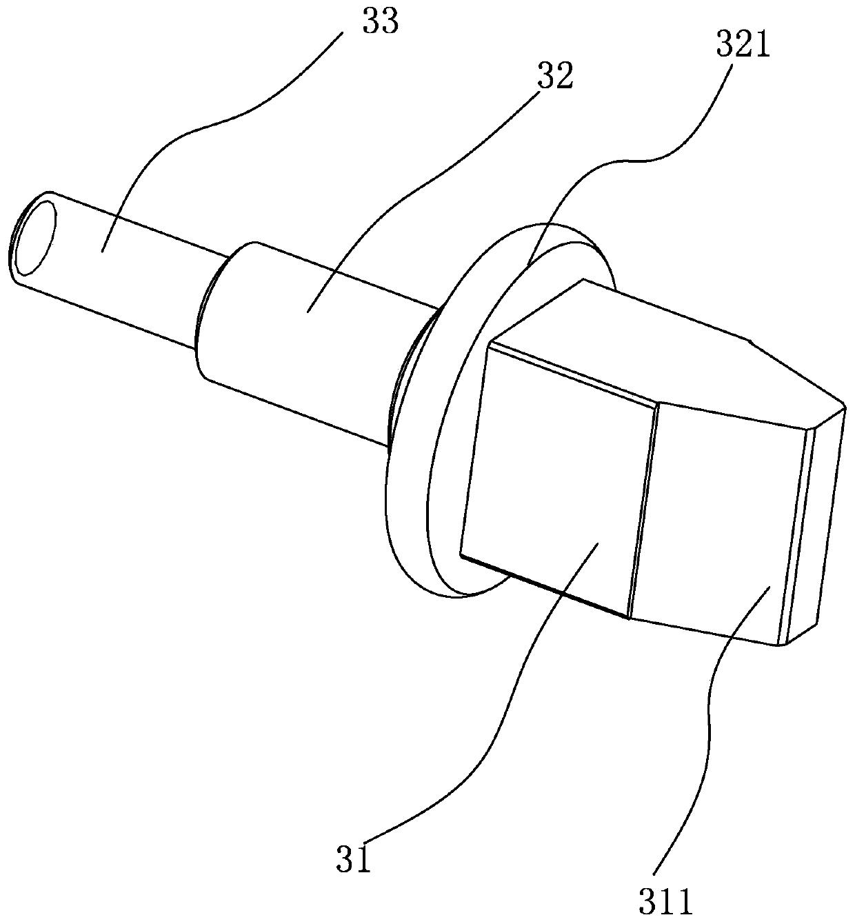
The invention relates to a rail-mounted inspection robot charging device and a working method thereof. The device comprises a rail assembly, a fixed charging assembly, a movable charging assembly anda battery; the fixed charging assembly comprises a fixed copper column connected with external power supply equipment, and the fixed copper column is connected to the rail assembly; the rail assemblyis slidably connected with a robot, the movable charging assembly comprises a movable copper column, the movable copper column comprises a copper column body and a shaft shoulder, the end, close to the fixed copper column, of the copper column body is connected with the shaft shoulder, and the edge of the shaft shoulder is arc-shaped; the end, close to the fixed copper column, of the robot is connected with the movable copper column, and the movable copper column is connected with the battery; and when the movable copper column abuts against the fixed copper column, the external power supply equipment charges the battery through the fixed copper column and the movable copper column. The contact position can be adaptively adjusted to make the movable copper column and the fixed copper column in close contact during charging of the robot, so the movable copper column and the fixed copper column are prevented from falling off, and safe and stable charging of the inspection robot is realized.

Description

technical field [0001] The invention relates to a rail-type inspection robot, and more specifically refers to a rail-type inspection robot charging device and a working method thereof. Background technique [0002] With the country's vigorous development of power infrastructure, the number of power distribution rooms has also increased linearly. There are a large number of power distribution cabinets in the power distribution room. Considering their particularity, they need to be monitored in real time. In order to save labor costs, there are inspection robots used in this kind of room on the market to conduct regular inspections. The inspection robot uses a rechargeable battery to power it. Since the robot has a long operating cycle and a large load, and feeds back the collected information to the terminal in real time, if the charging process cannot be carried out stably and safely, it will have a great impact on the inspection task of the robot. At the same time, it is ...

Claims


Application Information

Patent Timeline
Patent Type & Authority Applications(China)
IPC IPC(8): H02J7/00H01R13/02H01R13/629
CPCH01R13/02H01R13/629H02J7/0045
Inventor 王欣欣张文阔王秋阳杜强周起如
Owner SHENZHEN SUNWIN INTELLIGENT CO LTD
Learn More