
Brake device for vehicle

A technology of braking device and vehicle, which is applied in the direction of braking transmission device, braking action starting device, brake, etc., can solve the problem of reducing the responsiveness of pump motor and so on.

Active Publication Date: 2022-01-11
ADVICS CO LTD
View PDF5 Cites 0 Cited by
  • Summary
  • Abstract
  • Description
  • Claims
  • Application Information

AI Technical Summary

Problems solved by technology

In this case, if the rotation speed of the pump motor is excessively reduced, there is a possibility that the responsiveness of the increase in the rotation speed of the pump motor may be reduced. In the above-mentioned conventional vehicle braking device, there is room for improvement in this regard.

Method used


Image

  • Brake device for vehicle
  • Brake device for vehicle
  • Brake device for vehicle

Examples


Embodiment Construction

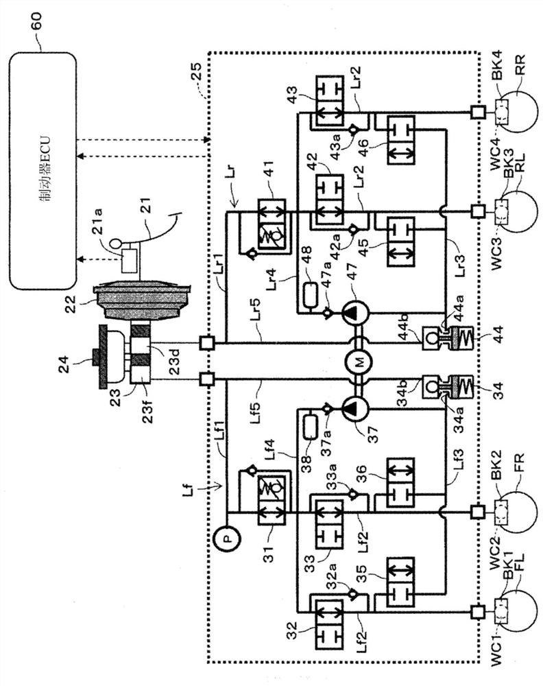
[0021] Hereinafter, embodiments of the vehicle brake device according to the present invention will be described with reference to the drawings. In addition, the same code|symbol is attached|subjected to the mutually identical or equivalent part among the following embodiment and each modification. In addition, each figure used for description is a conceptual figure, and the shape of each part may not necessarily be accurate.

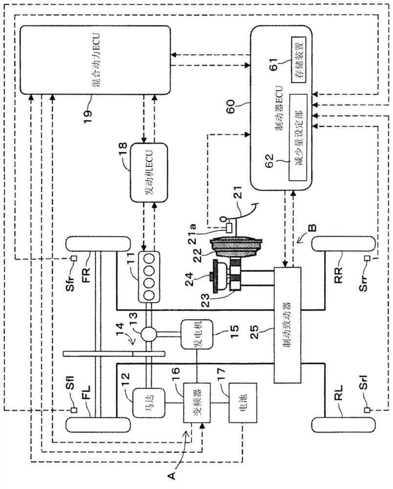
[0022] Such as figure 1 As shown, the vehicle braking device is applied to a hybrid vehicle. A hybrid vehicle is a vehicle in which drive wheels, such as left and right front wheels FL and FR, are driven by a hybrid system. The hybrid system is a power train that combines two types of power sources of the engine 11 and the motor 12 . In the case of the present embodiment, it is a parallel hybrid system in which both the engine 11 and the motor 12 directly drive the wheels. In addition, in the hybrid system, there is a series hybrid system in additio...


PUM


Abstract

The brake device for a vehicle of the present invention is provided with a reduction amount setting part (62) which sets the reduction amount of the rotational speed in the state of maintaining the control differential pressure or the state of reducing the pressure so that the pump motor ( The higher the probability that the pump (37, 47) needs to discharge the brake fluid from the time of the decrease of the rotation speed (Nd) of M) to the lapse of a predetermined time, the more the reduction amount of the rotation speed of the pump motor (M) becomes. Small.

Description

technical field [0001] The present invention relates to a vehicle brake device that applies a hydraulic braking force by a hydraulic brake unit to wheels according to a brake operation amount. Background technique [0002] Conventionally, for example, a brake device for a vehicle disclosed in Patent Document 1 below is known. This conventional vehicle braking device includes a regenerative braking device that applies regenerative braking force, a hydraulic brake device that applies hydraulic braking force using hydraulic pressure from a pump, and a brake ECU that controls the hydraulic brake device in cooperation with the regenerative braking device. . Furthermore, the brake ECU makes the motor for driving the pump decrease or become constant when the inclination of the target control hydraulic braking force that the hydraulic brake device should generate is reduced or constant when the regenerative braking force is applied by the regenerative braking device and the hydraul...

Claims


Application Information

Patent Timeline
Patent Type & Authority Patents(China)
IPC IPC(8): B60T13/122F04B49/06F04B49/20H02P29/00
CPCH02P29/00B60T13/20B60T17/02F04B49/06F04B49/20F16D61/00B60T1/10B60T13/586B60T13/146B60T13/662B60T13/686B60T7/042B60T8/409B60T2270/604B60T8/321B60T2240/00B60T2250/04B60T8/172B60T13/161
Inventor 葛谷贤石田康人浅野智孝山本贵之
Owner ADVICS CO LTD
Learn More