
Low-pollution flat grinding device

A low-pollution, flattening technology, which is applied in the direction of grinding drive devices, grinding/polishing safety devices, grinding machines, etc., can solve the problems of dust affecting the health of operators, achieve reduced adverse effects, simple design structure, and improved operation efficiency effect

Inactive Publication Date: 2018-07-27
ZHENGZHOU LONGWEI ELECTRONICS TECH CO LTD
View PDF10 Cites 0 Cited by
  • Summary
  • Abstract
  • Description
  • Claims
  • Application Information

AI Technical Summary

Problems solved by technology

[0004] The purpose of the present invention is to provide a low-pollution grinding device in order to solve the problem that the grinding device will generate a large amount of dust and affect the health of the operator.

Method used


Image

  • Low-pollution flat grinding device
  • Low-pollution flat grinding device
  • Low-pollution flat grinding device

Examples


Embodiment 1

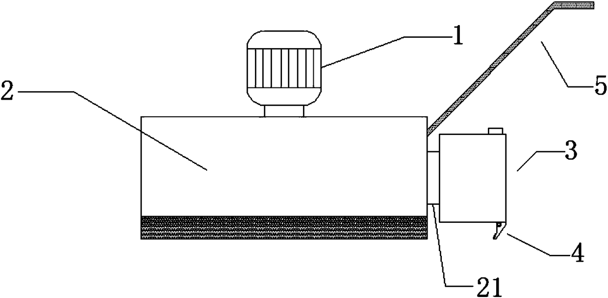
[0027] A low-pollution grinding device, comprising a first drive mechanism 1, a sanding disc 2 and a dust suction mechanism 3, a circular channel is provided on the outside of the grinding disc 2, and a dust suction port 6 is provided at the bottom of the circular channel, The ring channel is connected to the dust suction mechanism 3, and the bottom of the dust suction mechanism 3 is provided with a scraping mechanism 4. The dust collection mechanism 3 includes a dust collection box 31 , the control circuit and the dust suction assembly are located inside the dust collection box 31 , and the exhaust port 7 is located at the top of the dust collection box 31 . The control circuit includes a motor M connected to the working power supply at one end, the other end of the motor M is respectively connected to an inductor L and a capacitor C1, the other end of the inductor L is connected to a resistor R1, a bidirectional thyristor VS, and a capacitor C3, and the other end of the resis...

Embodiment 2

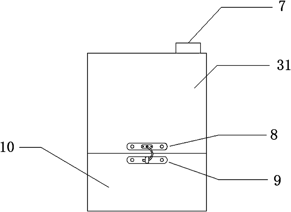
[0030] On the basis of Embodiment 1, a dust collection chamber 10 is provided at the inner bottom of the dust collection box 31, a buckle connection part 8 is provided on the dust collection box 31, and a buckle connection part 8 is provided on the dust collection chamber 10 to match The engaging part 9 of the dust collecting chamber 10 is connected with the dust collection box 31 by snapping. When the dust cannot be discharged into the external environment through the exhaust port 7, it will fall into the dust collection chamber 10, and the dust collection box 31 and the dust collection chamber 10 are connected by a buckle connection, so that the dust collection chamber 10 can be easily removed from the suction chamber. Taking out the dust box 31 also facilitates fixing the dust collecting chamber 10 in the dust collection box 31 . It achieves a good vacuuming effect and is easy to maintain.

Embodiment 3

[0032] On the basis of any of the above-mentioned embodiments, a push handle 5 is provided on the rear side of the sanding disc 2, which is convenient for the staff to control the direction of the device, and improves the convenience and reliability of the device operation.


PUM


Abstract

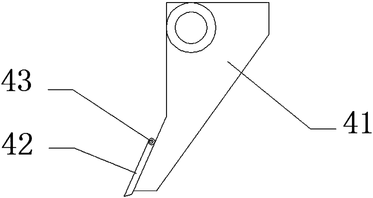
The invention discloses a low-pollution flat grinding device. The device comprises a first drive mechanism, a grinding abrasive disc and a dust suction mechanism; a ring type channel is arranged on the outer side of the grinding abrasive disc, a dust suction opening is formed in the bottom of the ring type channel, the ring type channel is connected with the dust suction mechanism, the dust suction mechanism comprises a dust suction box, a control circuit and a dust suction assembly are arranged in the dust suction box, an exhaust opening is formed in the upper portion of the dust suction box,and a dust collection chamber is arranged at the bottom in the dust suction box. A flat scraping mechanism comprises a flat scraping arm, a scraping piece fixing assembly is arranged on the flat scraping arm, a scraping piece is arranged between the scraping piece fixing assembly and the flat scraping arm, and the distance between the bottom of the scraping piece and the ground is not smaller than the distance between the bottom of the flat scraping arm and the ground. The device has the beneficial effects of being simple in structure, high in practicability, and capable of greatly reducing the side effect of the dust on the health of workers.

Description

technical field [0001] The invention relates to the technical field of machinery, in particular to a low-pollution grinding and flattening device. Background technique [0002] The wall grinder is a tool that replaces traditional manual workers with sandpaper to grind walls and objects, so as to achieve the purpose of smoothing, dust-free, and protecting the physical and mental health of workers. The floor grinder is a multi-functional machine that integrates different processes such as rapid floor grinding, floor hardening, epoxy floor treatment, floor leveling, grinding, and polishing. [0003] Before polishing the surface of ceramic tiles and stone slabs, especially ceramic tiles, after being fired in a kiln, the deformation is large and the surface is uneven. After consistency, the polishing process can be carried out again. However, when the traditional leveling machine processes the surface of porcelain wall and floor tiles and stone slabs, it will generate high-inte...

Claims


Application Information

Patent Timeline
Patent Type & Authority Applications(China)
IPC IPC(8): B24B7/18B24B55/06B24B47/12B24B41/00
CPCB24B7/18B24B41/00B24B47/12B24B55/06
Inventor 杨伯军
Owner ZHENGZHOU LONGWEI ELECTRONICS TECH CO LTD
Learn More