
Motor vehicle

A technology of motor vehicles and driving force, which is applied in the direction of motor vehicles, electric vehicles, control drives, etc., and can solve problems such as the decrease of driving torque

Inactive Publication Date: 2015-05-13
AUDI AG
View PDF5 Cites 0 Cited by
  • Summary
  • Abstract
  • Description
  • Claims
  • Application Information

AI Technical Summary

Problems solved by technology

During such driving situations, however, the currently available drive torque may be reduced due to the aforementioned parameters, so that high drive power is only available briefly

Method used


Image

  • Motor vehicle
  • Motor vehicle

Examples


Embodiment Construction

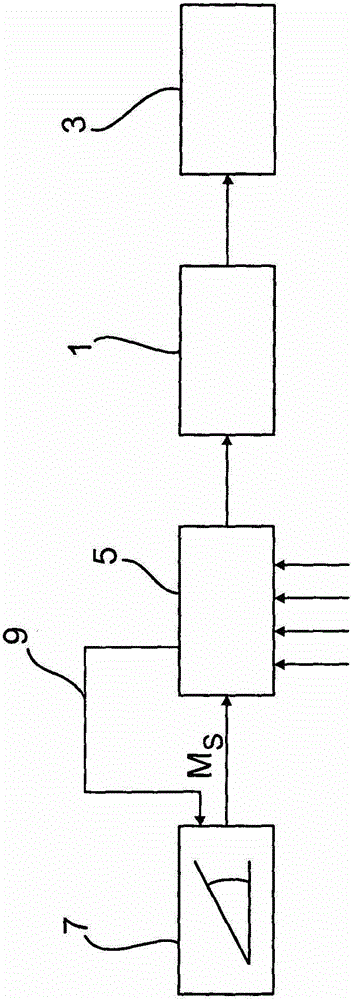
[0017] figure 1 A rough schematic view of the main drive components of a motor vehicle with an electric drive is shown in . The motor vehicle has an electric motor 1 as a drive unit, which is coupled via a drive train to a transmission 3 . The drive torque generated by the electric machine 1 can be transmitted to drive wheels, not shown, by means of the transmission 3 . Electric machine 1 can be controlled by means of electronic control unit 5 , which receives a plurality of vehicle operating parameters as input variables, for example the external temperature, the state of charge or temperature of a battery (not shown here) or other driving characteristic parameters. In addition, the control device 5 is connected to an accelerator pedal 7 . Depending on the deflection angle of the accelerator pedal 7, a and the desired torque M are assigned to the control device 5 S corresponding specified value. The control device 5 is based on the desired torque M reflecting the driver's...


PUM


Abstract

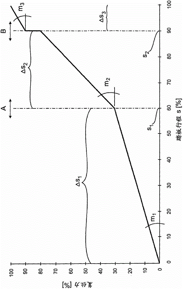
A motor vehicle has at least one drive unit for generating a drive torque, and has an accelerator pedal which is acted on with a restoring force and which can be adjusted by an actuating travel in order to predefine a setpoint torque. The motor vehicle also has a control device which actuates the drive unit on the basis of the setpoint torque. The control device additionally determines a presently available drive torque, and as a function of the presently available drive torque, varies the characteristic curve of the accelerator pedal, which expresses the restoring force versus the actuating travel of the accelerator pedal.

Description

technical field [0001] The invention relates to a motor vehicle. Background technique [0002] In motor vehicles with an electric drive, the available drive torque that can be provided by the electric machine depends on a number of influencing variables. Thus, for example, the drive power at the wheels may result for thermodynamic reasons depending on the external temperature, the driving profile (power requirement over time) and depending on the design / dimensioning of the cooling measures in the motor vehicle or on the drive components. Or traction is reduced, ie inhibited. Such suppression is responsible, for example, for component protection (avoiding overheating). This is especially true for the electrical power output from the battery and the power conversion in the drive system (power electronics and electric motor). Furthermore, the operational capability of the traction battery is related to other parameters such as state of charge, aging or temperature. [0003]...

Claims


Application Information

Patent Timeline
Patent Type & Authority Patents(China)
IPC IPC(8): B60K26/02B60W10/08B60L15/20
CPCB60K26/021B60L2240/443B60L2240/486B60W2510/0657B60W2510/0661B60W2510/083B60W2510/1025B60W2510/105B60W2540/10B60Y2200/91B60K2370/143Y02T10/72B60W50/16
Inventor W·施密特A·施陶博M·舒斯勒
Owner AUDI AG
Learn More