Clutch with gear rack and planetary mechanism

A technology of planetary mechanism and rack and pinion, which is applied in the field of clutches, can solve the problems of thermal fracture, large energy consumption, uneven pressing force, etc., and achieve the effects of improving fuel economy, improving reliability, and not being prone to fatigue fracture

Active Publication Date: 2017-08-11
SOUTH CHINA UNIV OF TECH
View PDF7 Cites 6 Cited by
  • Summary
  • Abstract
  • Description
  • Claims
  • Application Information

AI Technical Summary

Problems solved by technology

This type of clutch has the following disadvantages: 1) Since the force of the release finger of the diaphragm spring is not linearly related to the displacement of the release bearing, it is easy to produce insufficient pressing force when the clutch operating mechanism is actuated to engage the clutch. Uniform phenomenon, which in turn causes the clutch to generate self-excited vibration, which seriously affects the NVH (N refers to Noise, V refers to Vibration, H refers to Harshness) performance of the car
Because the axial stiffness of the diaphragm spring is very large, the power element is required to provide a large axial force, and it also consumes a lot of energy, which is not conducive to the fuel economy of the car
4) In the traditional diaphragm spring clutch, due to the harsh working environment and the structural characteristics of the clutch pressure plate, it is very easy to be thermally broken; at the same time, the diaphragm spring will also be fatigued and fractured, which seriously affects the reliability of the clutch

Method used


Image

  • Clutch with gear rack and planetary mechanism
  • Clutch with gear rack and planetary mechanism
  • Clutch with gear rack and planetary mechanism

Examples


Embodiment Construction

[0033] The purpose of the present invention will be further described in detail through specific examples below, and the examples cannot be repeated here one by one, but the implementation of the present invention is not therefore limited to the following examples.

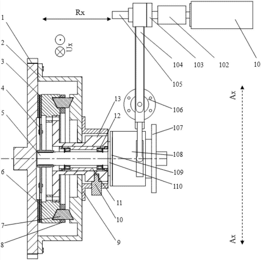
[0034] figure 1 The general assembly diagram of the structure of the invention is shown. Wherein, the clutch cover assembly mechanism is a sectional view, the radial direction is Ax, the axial direction is Rx, and the circumferential rotation direction is Ux.

[0035]A clutch with a rack and pinion and a planetary mechanism, including a clutch cover assembly mechanism and a clutch engagement-separation control mechanism, the clutch cover assembly mechanism includes a fixedly connected flywheel 1 and a clutch cover 2, which are arranged on the The transmission input shaft 5 in the clutch cover 2, the driven plate 4 and the pressure plate 6 are sequentially arranged on the transmission input shaft 5 along the direc...


PUM


Abstract

The invention discloses a clutch with a gear rack and a planetary mechanism. The clutch comprises a clutch cover assembly mechanism and a clutch connection and disconnection operation mechanism, wherein the clutch cover assembly mechanism comprises a flywheel, a clutch cover, a transmission device input shaft, a driven disc and a pressing disc; the driven disc and the pressing disc are sequentially arranged on the transmission device input shaft; a hollow grooved cam is fixedly arranged at the end far from the flywheel of the clutch cover; a thrust sleeve is arranged on the transmission device input shaft in a rotating manner; the periphery of the thrust sleeve is in sliding connection with a driving neck through a spline; one end of the driving neck is fixedly connected with the pressing disc, and the other end of the driving neck is provided with a locating slider in sliding fit with a groove of the grooved cam; and a planetary gear mechanism is arranged between the pressing disc and the inner end surface of the clutch cover. Compressing force is linearly increased with the displacement of a separating bearing, and the power driving element of an operating mechanism is conveniently controlled, so that the reliability is high, and the service life is long. The power of the power driving element is low, so that the energy consumption of the system is reduced.

Description

technical field [0001] The present invention relates to a clutch for mechanical automatic transmission, in particular to a clutch pressure plate with a rack and pinion and a planetary mechanism, and a clutch including the clutch pressure plate. The meshing rotation pushes the pressure plate to move axially to realize the engagement and separation of the clutch. Background technique [0002] In the power system of a vehicle, the clutch is a key component connecting the engine and the gearbox. At present, the clutches used in automotive mechanical automatic transmissions basically use traditional diaphragm spring clutches. This type of clutch has the following disadvantages: 1) Since the force of the release finger of the diaphragm spring is not linearly related to the displacement of the release bearing, it is easy to produce insufficient pressing force when the clutch operating mechanism is actuated to engage the clutch. The phenomenon of uniformity will cause the clutch t...

Claims


Application Information

Patent Timeline
Patent Type & Authority Applications(China)
IPC IPC(8): F16D13/38F16D13/60F16D13/58F16D13/70
CPCF16D13/38F16D13/58F16D13/60F16D13/70
Inventor 上官文斌刘雪莱
Owner SOUTH CHINA UNIV OF TECH
Why Eureka
Try Eureka