Actuating device for a rotatable closure part of a valve

a technology of a rotatable closure and an actuating device, which is applied in the direction of valve details, valve arrangement, operating means/releasing devices, etc., can solve the problems of stroke-dependent and thus indirect rotation angle limitation, hardly stable drive shaft, and inability to adjust the rotation angle of the drive shaft, etc., to achieve the effect of reducing the diameter small drive torque and reducing the production cost of the actuating devi

Active Publication Date: 2018-05-08
GEA TUCHENHAGEN GMBH
View PDF20 Cites 4 Cited by
  • Summary
  • Abstract
  • Description
  • Claims
  • Application Information

AI Technical Summary

Benefits of technology

[0016]A first fundamental inventive solution consists in that the drive shaft has a two-sided and thereby respectively direct, radial mounting in a bearing casing permanently connected with the housing or designed in it. This direct radial mounting creates the beneficial prerequisites for a high mounting accuracy.
[0033]Valves with a very small nominal width generally require an actuating device, which only needs to generate a correspondingly small drive torque. This drive torque in turn requires a drive piston with a relatively small outer diameter and preferably designed as one piece with a piston skirt with approximately the same diameter because a reduction of its diameter is hardly possible due to the constructive provisions to be housed in it. In the case of this design, the arrangement of a return spring surrounding the piston skirt on the outside is not possible. In order to solve this arrangement problem of the return spring in an advantageous manner, one suggestion provides that the at least one return spring is arranged on one hand within the first piston skirt and its axial support is on a first piston floor of the first drive piston and that on the other hand the receiver and axial support of the at least one return spring is provided in a front-side recess in the drive shaft. The position stability of the return spring is increased when it, as is suggested, is designed split in two in the longitudinal direction and its neighboring ends are received in an intermediate piece, which is guided in an axially displaceable manner preferably in the front-side recess.

Problems solved by technology

While the movement kinematics of the known actuating device is achieved with relatively simple means, it only works at the price of a hardly stable and imprecise drive-piston-side radial mounting of the drive shaft.
Moreover, the rotation angle limitation of the drive shaft takes place in a stroke-dependent manner and thus imprecisely since the stroke movement of the drive piston or of the piston skirt connected with it is limited by unrevealed impacts and not the rotary movement.
The rotation angle limitation of the drive shaft takes place in an axial idle position assumed by the piston under the effect of a return spring on an axially adjustable adjustment element.
This thus involves a stroke-dependent and thus indirect rotation angle limitation.
The rotation angle limitation of the drive shaft takes place through axial end position limitation of the piston on the covers.
This thus involves a stroke-dependent and thus indirect rotation angle limitation.
The rotation angle limitation of the drive shaft takes place through axial end position limitation of the piston on the covers.
This thus involves a stroke-dependent and thus indirect rotation angle limitation.
The rotation angle limitation of the inner cylinder takes place through axial end position limitation of the sliding casings on the closed ends of the axially oriented slit.
This thus involves a stroke-dependent and thus indirect rotation angle limitation.
The rotation angle limitation of the drive shaft takes place on one hand through axial end position limitation of the piston on the other cover of the housing and on the other hand through placement of the sliding rollers on the closed ends of the slits.
This thus involves a stroke-dependent and thus indirect rotation angle limitation.
The two known rotation angle limitations are relatively complex and the end position limitation of the drive shaft does not take place directly on the stationary housing, but rather indirectly via a locking cam or via two guide rods, wherein an adjustment of the angle of rotation can only take place by reworking the circular-segment-like recess on the stop element or respectively on the stop segment.

Method used


Image

  • Actuating device for a rotatable closure part of a valve
  • Actuating device for a rotatable closure part of a valve
  • Actuating device for a rotatable closure part of a valve

Examples


second embodiment

[0058]The structure of the two-piece or respectively two-part second drive piston 40 according to FIGS. 5, 6 (preferred second embodiment) is described below. Its arrangement and function within the actuating device 1 described above mainly corresponds with that of the first drive piston 4 in the FIGS. 1 to 4, and the above description is also transferable without restrictions to the A description to this effect is thus foregone.

[0059]The separation of the second drive piston 40 is provided in at least one casing surface of an outer piston 40a and of an inner piston 40b surrounding the axis of rotation A concentrically. In the exemplary embodiment, they are two radially spaced casing surfaces, so that a radially inward directed projection 40a.3 is formed on the outer piston 40a and a complementary return 40b.3 is formed on the inner piston 40b. The outer piston 40a and the inner piston 40b are preferably interconnected in a form-fitting and releasable manner. But the joining of the...

first embodiment

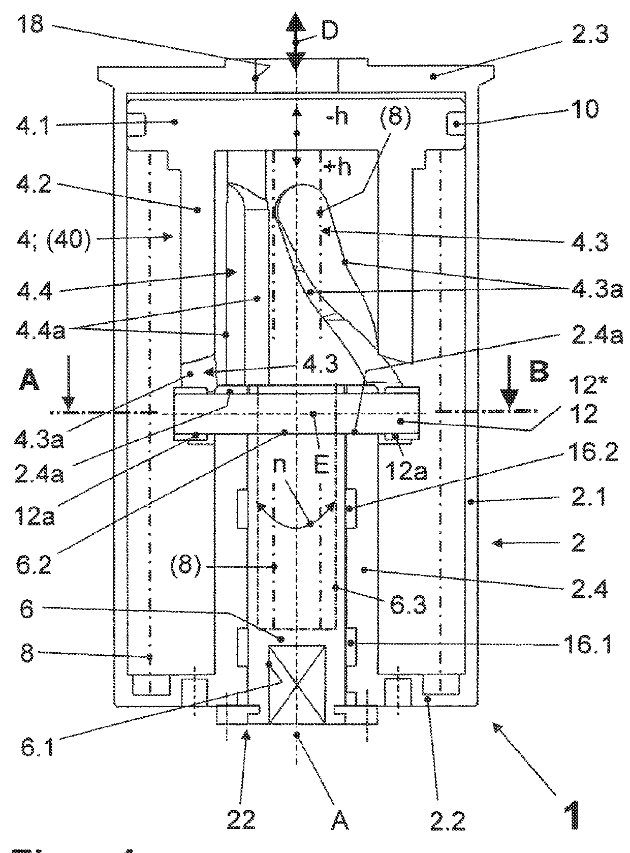
[0063]FIG. 5 shows a preferred radial and axial mounting of the drive shaft 6. For this purpose, the first bearing 16.1 and the second bearing 16.2 for the radial and additionally also for the axial mounting (axial bearing 22) of the drive shaft 6 are provided in the bearing casing 2.4 at a distance from each other. This mounting is also transferable to the actuating device 1 with the first drive piston 4 designed as one part. The second bearing 16.2 neighboring the respective drive piston 4, 40 receives an axial force oriented towards it and the first bearing 16.1 receives an opposite axial force, respectively exerted preferably by a shoulder of the drive shaft 6 assigned to the respective bearing 16.2, 16.1. The drive shaft 6 is sealed in a pressurizing-medium-tight manner in the area of the first bearing 16.1 with respect to it by means of a first seal 26 and the first bearing 16.1 with respect to the bearing casing 2.4 by means of a second seal 27. This sealing is required when,...


PUM


Abstract

The invention relates to an actuating device for a rotatable closure part of a valve, in particular a pneumatically or hydraulically actuatable rotary drive for a disk or throttle valve, with a housing, in which a drive piston that is sealed from a cylindrical housing casing is arranged and is suppliable on one side with a pressurizing medium, which preferably has a tubular piston skirt, with a drive shaft, which is guided on one side out of the housing and drives in a rotating manner the closure part indirectly or directly, wherein the drive piston executes either an axial shift movement against the effect of at least one return spring in the case of a one-sided supply with the pressurizing medium or a back and forth shift movement in the case of an alternating supply with a pressurizing medium, wherein the piston skirt experiences an axially oriented guidance in the housing via at least one axial groove formed in it, into which a straight-line guide cam permanently connected with the housing engages, and wherein the piston skirt has at least one helical groove arranged in it, into which a drive bolt permanently arranged on or in the drive shaft is arranged, so that the radially and axially mounted drive shaft experiences a rotation around the axis of rotation due to the axial shift movement of the drive piston oriented in the direction of its axis of rotation.

Description

CROSS-REFERENCE TO RELATED APPLICATIONS[0001]This application is a U.S. National Stage application which claims priority to PCT / EP2012 / 003541, filed on Aug. 21, 2012, which claims priority to DE 10 2011 116 627.4, filed Oct. 20, 2011. The claims have been amended to conform to U.S. practice and to eliminate multiple dependent claims.BACKGROUND OF THE INVENTION[0002]An actuating device of the generic type (also referred to as a rotary drive), in which a drive piston executes an axial shift movement against the effect of at least one return spring in the case of a one-sided supply with a pressurizing medium, is described in EP 0 599 770 A2. In a tubular piston skirt releasably connected with the drive piston, two diametrically arranged axial grooves are arranged for the straight-line guide of the drive piston and a single cam guide groove tilted against the axial movement direction of the drive piston is arranged in order to generate the rotary movement of the drive shaft. The drive s...

Claims


Application Information

Patent Timeline
Patent Type & Authority Patents(United States)
IPC IPC(8): F16K31/16F15B15/06F16K31/122F16K31/528
CPCF15B15/068F16K31/5282F16K31/16F16K31/1221
Inventor BURMESTER, JENSSUDEL, MATTHIAS
Owner GEA TUCHENHAGEN GMBH
Why Eureka
Try Eureka