
Tracking device for sun and satellite

A satellite tracking and sun technology, applied in the field of sun or satellite tracking devices, can solve the problems of inapplicability, complicated instrument structure, and little reduction in manufacturing cost, and achieve simplification of transmission mechanism, simplification of tracking controller, and small angle range Effect

Active Publication Date: 2013-10-16
NANJING ZHONGKE ASTROMOMICAL INSTR +1
View PDF10 Cites 5 Cited by
  • Summary
  • Abstract
  • Description
  • Claims
  • Application Information

AI Technical Summary

Problems solved by technology

In high-end tracking equipment, such as a class of instruments used for astronomical observation and measurement, although their tracking systems can meet the requirements of solar energy applications, their structures are complex and expensive, and cannot be applied
In some patent documents that are applied to solar tracking, such as Chinese patent document 200510094900.8; 200780050920.2, most of them use horizontal motion devices, which require continuous tracking in both directions of azimuth and altitude angles, and the mechanical transmission mechanisms all use The traditional deceleration method uses gears, worm gears, cams, planetary gears, parallel four-bar linkages, etc., so the instrument structure is still complicated, the manufacturing cost is not reduced, and the overall cost is still relatively high; in addition, there are also patent documents such as Chinese patents 201010589870.9, 201120174363.9, etc. propose to use electric push rods to drive the sun tracking and satellite polar axis antennas, but due to the limitations of their own structure and usage methods, such technical solutions can only be used for driving small angle ranges. More than 100 degrees, it can meet the requirements for altitude angle (0~90°) or declination angle (-23.5°~+23.5°), but not for azimuth angle (±99°) and hour angle (±75°) , and they don't address an Achilles' heel of such mechanisms, which is that the moving parts are exposed, the packaging is troublesome, and it will cause rust and fail to work in rainy and snowy days

Method used


Image

  • Tracking device for sun and satellite
  • Tracking device for sun and satellite
  • Tracking device for sun and satellite

Examples


Embodiment Construction

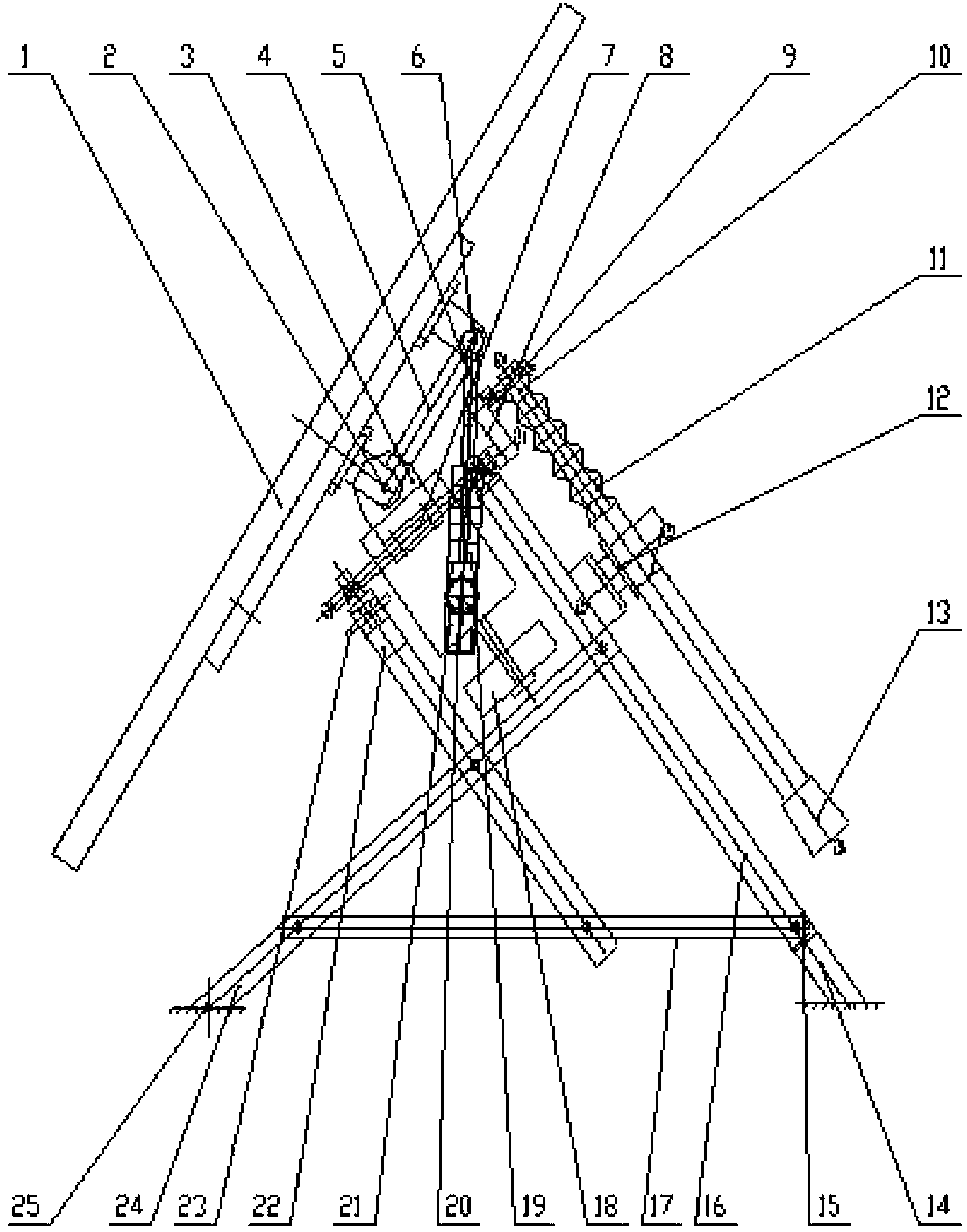
[0024] Such as figure 1 As shown, as an embodiment of the present invention, this is an equatorial motion device driven by a two-axis, its load is a solar panel 1, which is installed on the declination axis 2 through a back frame and a support, and supports The bracket 3 of the declination axis 2 is mounted on the polar axis 7. The polar axis 7 is fixed on the front column 22 and the rear column 16 through the bearing seats at both ends. The installation inclination angle Φ of the polar axis is the The included angle is the local latitude. In Nanjing, Φ=32°, the best inclination angle of solar panels is β, and the relationship between the two is shown in the following formula:

[0025] β=Φ-δ

[0026] This formula represents the best inclination angle at noon. At this time, the normal line of the solar panel 1 is parallel to the incident rays of sunlight, and the declination angle δ in this formula can be approximated by the following formula:

[0027] δ = ( twenty three ...


PUM


Abstract

The invention aims at solving a technical problem that a tracking device that is used for the sun and a satellite and is capable of meeting application requirements of solar energy engineering and a satellite polar shaft antenna is needed to be provided. The tracking device comprises a load support, a tracking transmission mechanism, and a pedestal of the tracking transmission mechanism. The tracking transmission mechanism includes two moving shafts; one of the moving shafts is a polar shaft that is parallel to a rotation axis of the earth and is used for realizing motions at east-west directions and continuously tracking a change of an hour angle at a constant speed; and the other moving shaft is a declination shaft that is perpendicular to the polar shaft and is used for realizing north-south motions to change a declination angle. And the polar shaft and the declination shaft are respectively driven by a polar shaft tracking transmission mechanism and a declination shaft tracking transmission mechanism. According to the invention, the provided tracking device has the advantages of simple structure, low cost, reliable running, and low self power consumption and can be widely applied to solar energy engineering and satellite polar shaft antenna equipment.

Description

Technical field [0001] The invention relates to a celestial body tracking device, in particular to a sun or satellite tracking device mainly used in solar energy engineering and satellite polar axis antenna equipment. Background technique [0002] Modern science and technology have been quite mature in tracking celestial bodies (such as the sun and stars) and man-made space moving bodies (such as satellites, missiles, and spacecraft). However, in certain fields, we must also consider its manufacturing costs to obtain more Good application value. For example, in solar photovoltaic power generation and thermal power generation, the cost of power generation must be compared with conventional energy sources, and the gap between the two must be gradually narrowed in order to obtain environmentally friendly and cheap clean energy to promote the application of solar power generation. [0003] To reduce the cost of solar power generation, it is essential to reduce the cost of tracking ins...

Claims


Application Information

Patent Timeline
IPC IPC(8): G05D3/10
Inventor 刘明星朱庆生万里郭荣华龚雨华
Owner NANJING ZHONGKE ASTROMOMICAL INSTR
Learn More