Fishing reel capable of automatically releasing magnetic force slow-down function

A fishing reel and magnetic technology, applied in fishing reels, fishing, applications, etc., can solve the problems of troublesome operation, delayed reeling time, affecting the control of the crank handle, etc., and achieve the effect of convenient assembly and reasonable structure

Pending Publication Date: 2020-04-28
陈姿羽
View PDF3 Cites 0 Cited by
  • Summary
  • Abstract
  • Description
  • Claims
  • Application Information

AI Technical Summary

Problems solved by technology

If you continue to use habitual movements to shake the handle and forget to turn off the magnetic slow down function, then the magnetic line of force on the magnet base will still produce resistance to the rotation of the wire wheel, making it difficult to take up the line; if the magnetic slow down function is turned off by a button or other means , it is more troublesome in operation, and the time for taking up the line is delayed, which may easily cause the fish to run away
[0005] The existing magnetic slow down function is equipped with a manual magnetic control knob, which generally includes two types, one is set on the same side as the handle, and the other is set on the non-side of the handle. The structures of the two are different. , Compared with the setting method on the same side, the setting method on the opposite side is more convenient to operate in actual use (the setting method on the same side needs to be pressed with the hand that controls the handle, which will easily affect the control of the handle)

Method used


Image

  • Fishing reel capable of automatically releasing magnetic force slow-down function
  • Fishing reel capable of automatically releasing magnetic force slow-down function
  • Fishing reel capable of automatically releasing magnetic force slow-down function

Examples


Embodiment Construction

[0018] The present invention will be described in further detail below in conjunction with the accompanying drawings and specific embodiments.

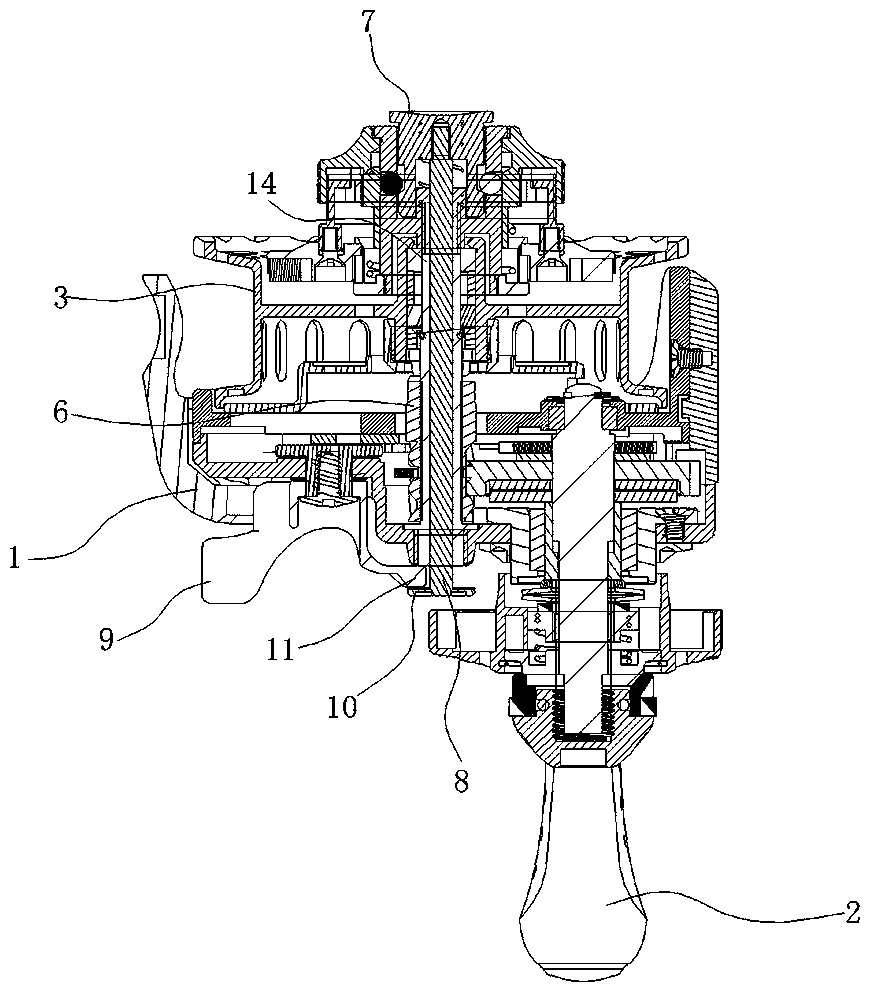
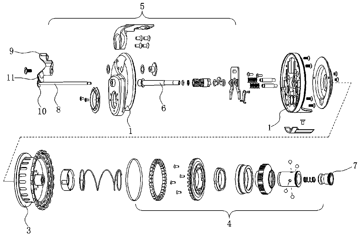
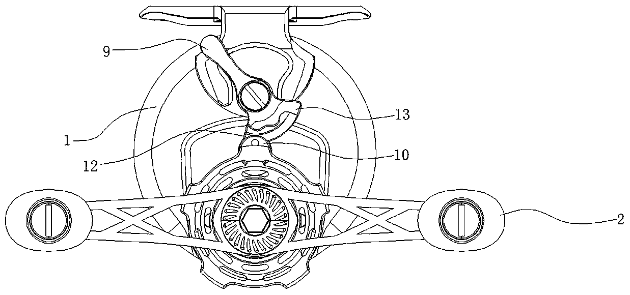
[0019] refer to Figure 1 to Figure 5 , a fishing reel that automatically releases the magnetic slow down function, comprising a fishing reel main body 1, a crank handle 2 located on one side of the fishing reel main body 1, a reel 3 driven by the crank handle 2 through a transmission assembly, and a fishing reel located On the other side of the wire wheel main body 1 is a magnetic slow-down assembly 4 for adjusting the speed of the wire wheel 3, a clutch assembly 5 that controls the rotation of the wire wheel 3 freely or driven by the rocker 2, and the transmission assembly includes a main shaft 6, The wire wheel 3 is sleeved on the main shaft 6, the magnetic slow down assembly 4 includes a magnetic control knob 7, and the magnetic control knob 7 is located on the side away from the crank handle 2. The main shaft 6 is provided with ...


PUM


Abstract

A fishing reel capable of automatically releasing magnetic force slow-down function is disclosed. The fishing reel comprises a fishing reel body, a rocker on one side of the fishing reel body, a linereel driven to rotate by the rocker through a transmission component, a magnetic force slow-down component on the other side of the fishing reel body and used to adjust the rotational speed of the line reel and a clutch component used to control the free rotation of the line reel or the rotation of the line reel driven by the rocker. The transmission component includes a main shaft, the line reelis sleeved on the main shaft, and the magnetic force slow-down component includes a magnetic force control button. The magnetic force control button is located on the one side far away from the rocker. The main shaft is provided with a movable shaft, and one end of the movable shaft is connected to the magnetic force control button. When the clutch component is switched from the disengaged state to the engaged state, the clutch component abuts on the movable shaft and drives the magnetic force control button through the movable shaft to close magnetic force slow-down component. The invention can realize the automatic reset function for the magnetic force slow-down structure disposed on the opposite side of the magnetic force control button and the rocker without additional manual operation, and can eliminate the magnetic force at the first time without delaying the time of taking-up.

Description

technical field [0001] The invention relates to the technical field of fishing reels, in particular to a fishing reel with the function of automatically releasing the slow-down function of magnetic force. Background technique [0002] With the improvement of people's living standards, people's hobbies are also developing rapidly. Fishing is an outdoor sport, the goal is to catch fish out of the water with fishing gear, and fishing is not limited to gender and age, adults and children like it. Fishing is close to nature and cultivates sentiment, which is highly sought after by the majority of enthusiasts. [0003] Some fishing reels on the market will be equipped with two structures of reel clutch and magnetic slow down. In the existing structure, the two structures of the wire wheel clutch and the magnetic slow down are set independently of each other, and need to be controlled and switched separately, and the operation is relatively cumbersome. [0004] In the actual sce...

Claims


Application Information

Patent Timeline
Patent Type & Authority Applications(China)
IPC IPC(8): A01K89/02
CPCA01K89/02
Inventor 陈姿羽其他发明人请求不公开姓名
Owner 陈姿羽
Why Eureka
Try Eureka