Lamp manufacturing and punching device

A technology for punching devices and lamps, applied in positioning devices, feeding devices, manufacturing tools, etc., can solve the problems of debris flying around, operator injury, debris blocking, etc., to improve flexibility and increase contact area , Easy to disassemble and replace

Inactive Publication Date: 2020-04-28
南京雷仕光电科技有限公司
View PDF6 Cites 9 Cited by
  • Summary
  • Abstract
  • Description
  • Claims
  • Application Information

AI Technical Summary

Problems solved by technology

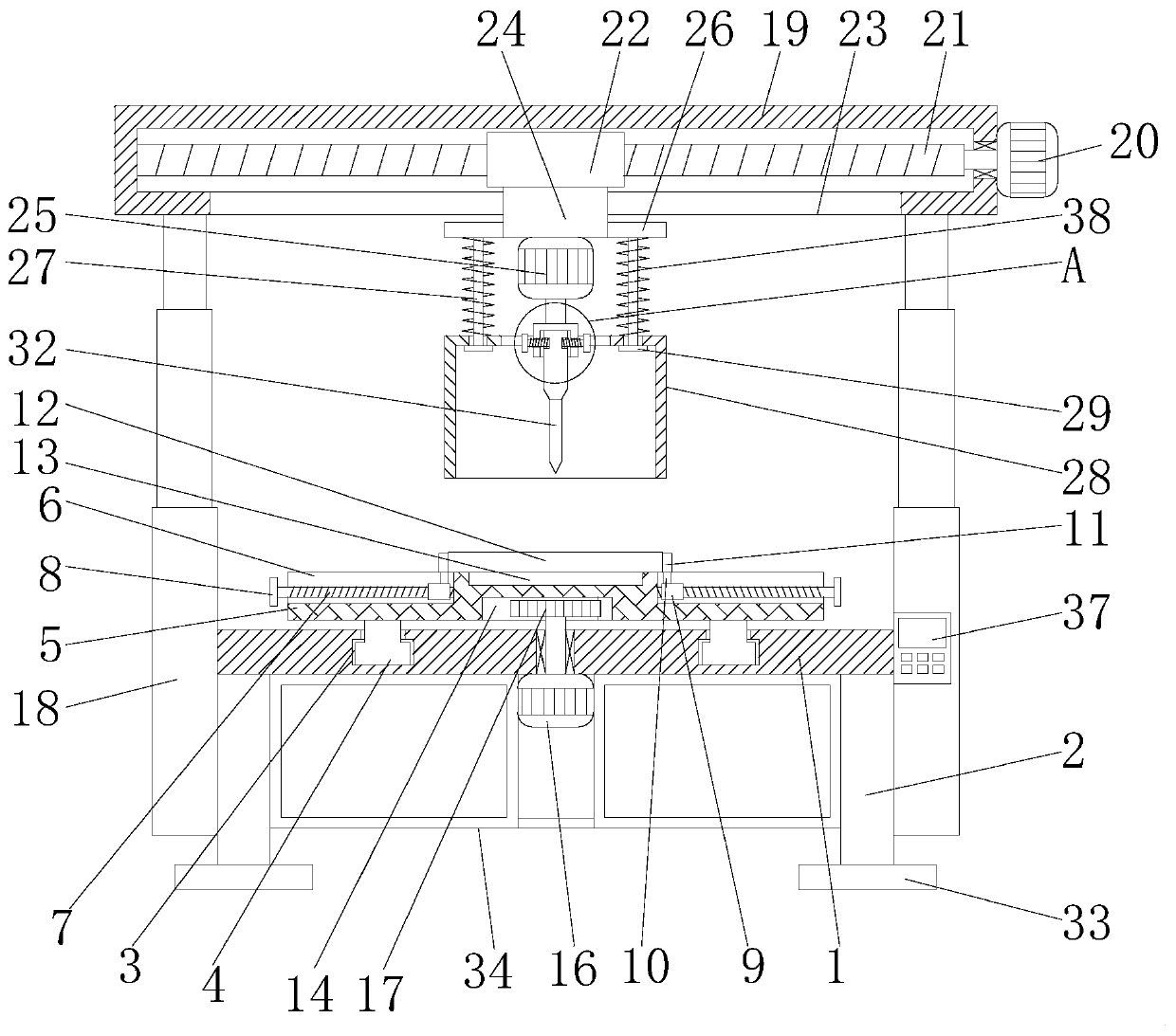
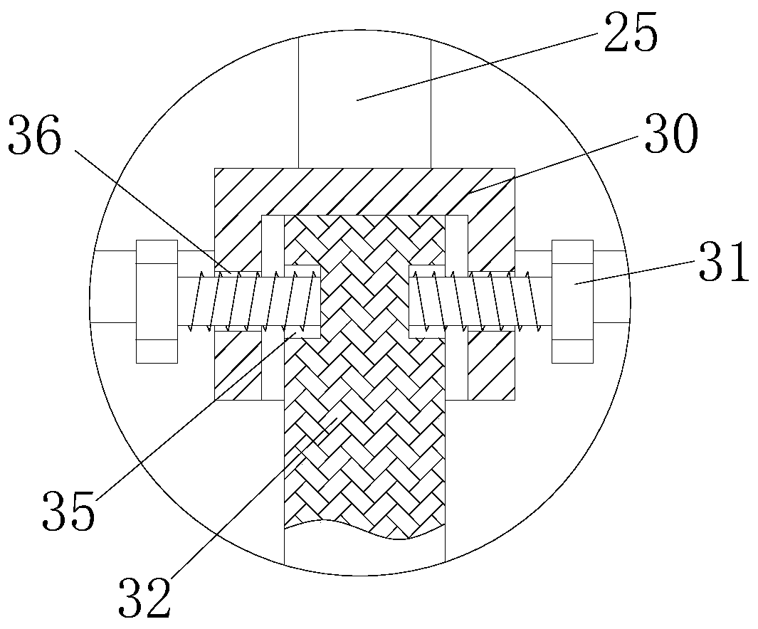
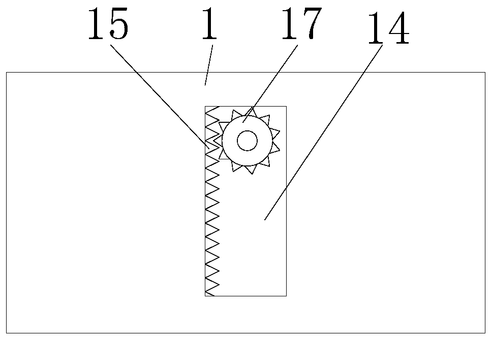
[0004] The purpose of the present invention is to provide a drilling device for lamp manufacturing, which can adjust the longitudinal position of the lamp board and the lateral position of the drill rod, which improves the flexibility of drilling and shields the debris generated during the drilling process. The advantage is that the existing lamp board drilling equipment can not adjust the position of the lamp board after the lamp board is fixed, and it is inconvenient to adjust the position of the drill rod, which reduces the flexibility of drilling and cannot be broken during the drilling process. It is easy to make the debris fly around and cause injury to the operator

Method used


Image

  • Lamp manufacturing and punching device
  • Lamp manufacturing and punching device
  • Lamp manufacturing and punching device

Examples


Embodiment Construction

[0022] The following will clearly and completely describe the technical solutions in the embodiments of the present invention with reference to the accompanying drawings in the embodiments of the present invention. Obviously, the described embodiments are only some, not all, embodiments of the present invention. Based on the embodiments of the present invention, all other embodiments obtained by persons of ordinary skill in the art without making creative efforts belong to the protection scope of the present invention.

[0023] In the description of the invention, it should be noted that the terms "upper", "lower", "inner", "outer", "front end", "rear end", "both ends", "one end", "another end" etc. The indicated orientation or positional relationship is based on the orientation or positional relationship shown in the drawings, and is only for the convenience of describing the present invention and simplifying the description, rather than indicating or implying that the referre...


PUM


Abstract

The invention discloses a lamp manufacturing and punching device. The lamp manufacturing and punching device comprises a flat plate and bolts, wherein supporting legs are fixedly connected to the twosides of the bottom of the flat plate; sliding grooves are formed in the two sides of the top of the flat plate; sliding blocks are in sliding connection with inner cavities of the sliding grooves; the tops of the sliding blocks extend to the outer parts of the sliding grooves and are fixedly connected with a moving table; transverse grooves are formed in the two sides of the top of the moving table; and first threaded rods are movably connected to the inner walls of the transverse grooves. The lamp manufacturing and punching device has the beneficial effects that the longitudinal position ofa lamp panel can be adjusted, the transverse position of a drill rod can be adjusted, the drilling flexibility is improved, and chippings generated in the drilling process are shielded; and the problems that after an existing lamp panel drilling device fixes the lamp panel, the position of the lamp panel cannot be adjusted, the position of the drill rod cannot be conveniently adjusted, the drilling flexibility is reduced, the chippings cannot be shielded in the drilling process, the chippings are likely to fly to the periphery, and injuries are likely to be brought to operators are solved.

Description

technical field [0001] The invention relates to the technical field of lamp manufacturing, in particular to a punching device for lamp manufacturing. Background technique [0002] The role of lighting fixtures is not limited to lighting, but also the eyes of the home, more often it plays a decorative role, so the choice of lighting fixtures is much more complicated, it not only involves safety and energy saving, but also will It involves many factors such as material, type, style and taste. A good lighting decoration may become the soul of decoration at once. There are many types of lighting fixtures, including chandeliers, ceiling lamps, table lamps, floor lamps, wall lamps, spotlights, etc.; there are also many colors of lighting fixtures, such as colorless, pure white, pink, light Blue, light green, golden yellow, creamy white. When choosing a lamp, don't just consider the shape and price of the lamp, but also consider the brightness. The definition of brightness should...

Claims


Application Information

Patent Timeline
Patent Type & Authority Applications(China)
IPC IPC(8): B23B41/00B23B47/20B23Q3/06B23Q11/00
CPCB23B41/00B23Q3/062B23Q5/28B23Q11/0042
Inventor 汪菊龙
Owner 南京雷仕光电科技有限公司
Why Eureka
Try Eureka