Adjustable loom needle bed

An adjustable, needle seat technology, used in textiles and papermaking, knitting, weft knitting, etc., can solve the problems of inability to adjust the needle up and down of the textile machine, the needle seat does not have a buffer structure, and the effect of textile materials is poor. Cost and manpower and material resources, avoid fixed height, avoid the effect of pin loss

Inactive Publication Date: 2020-04-28
JIASHAN SHENGSHIDE FUR GARMENT
View PDF0 Cites 2 Cited by
  • Summary
  • Abstract
  • Description
  • Claims
  • Application Information

AI Technical Summary

Problems solved by technology

[0002] Most of the traditional needle bases are fixedly connected to the needles of textile machines through simple fixing devices, resulting in the inability to adjust the lifting and moving left and right of the textile machine needles according to actual requirements, and most of the needle bases do not have a certain buffer structure , resulting in a large number of broken needles during use. Therefore, we propose a textile machine needle seat to fix, adjust and protect steel needles. When the existing textile machine is in use, the needle seat of the textile machine The position of the steel needles on the machine cannot be adjusted, and the position of each steel needle cannot be adjusted according to different textile materials. The effect of carding textile materials is poor, and there are few types of textile materials that can be adapted. Therefore, an adjustable needle seat for textile machines is needed. improve the above problems

Method used


Image

  • Adjustable loom needle bed
  • Adjustable loom needle bed
  • Adjustable loom needle bed

Examples


Embodiment Construction

[0020] The following will clearly and completely describe the technical solutions in the embodiments of the present invention with reference to the accompanying drawings in the embodiments of the present invention. Obviously, the described embodiments are only some, not all, embodiments of the present invention. Based on the embodiments of the present invention, all other embodiments obtained by persons of ordinary skill in the art without making creative efforts belong to the protection scope of the present invention.

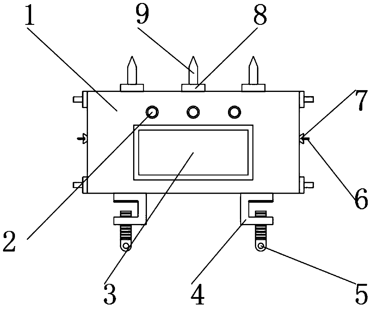
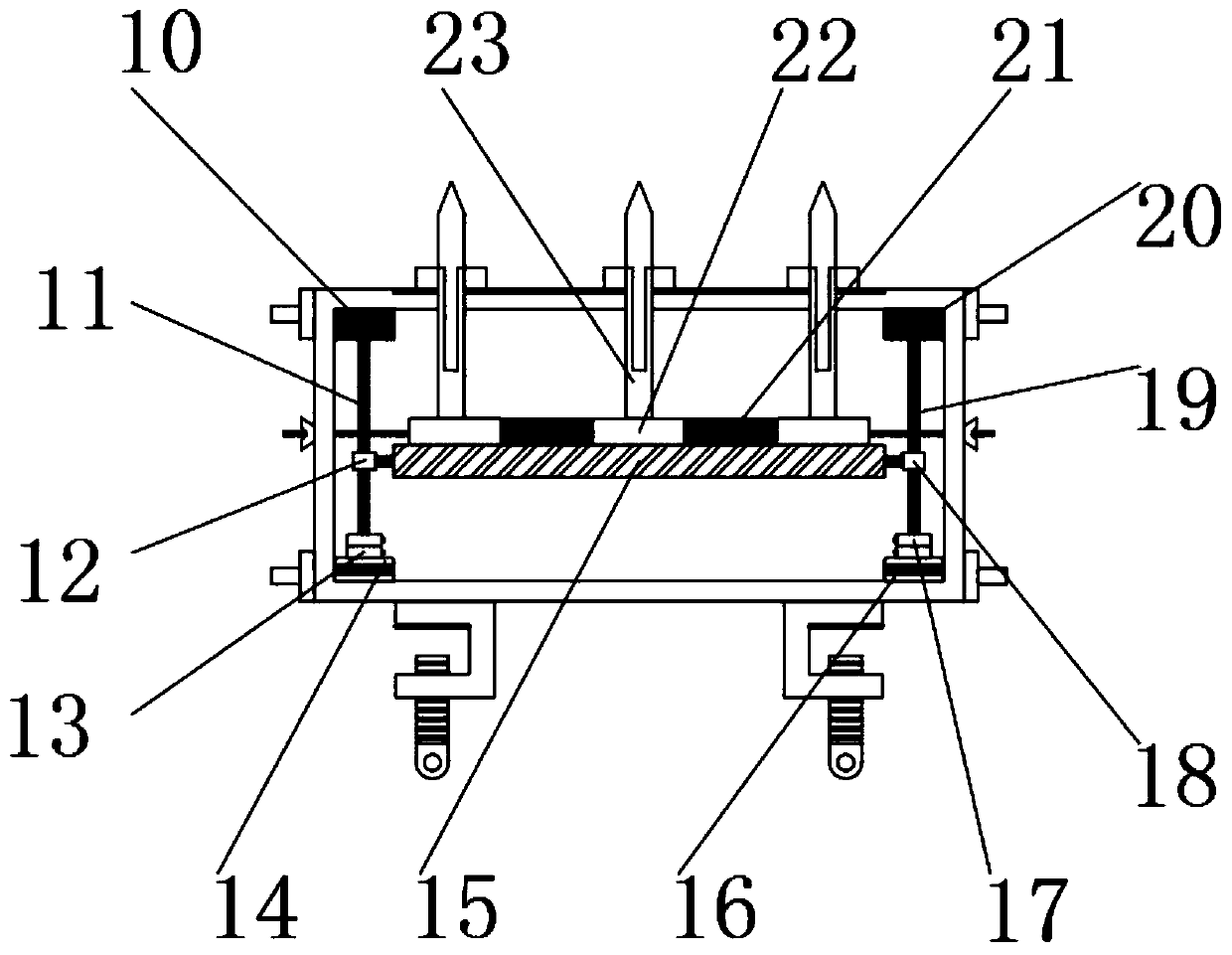
[0021] see Figure 1-3 , the present invention provides a technical solution: an adjustable needle holder of a textile machine, comprising a needle holder housing 1, a display screen 3 and a card holder 4, the outer front end of the needle holder housing 1 is provided with a control button 2 and a display screen 3, through The control button 2, the display screen 3, the first motor 14 and the second motor 16 are set. This design realizes the automatic adjustme...


PUM


Abstract

The invention relates to the technical field of textile equipment, in particular to an adjustable loom needle bed. The adjustable loom needle bed comprises a needle bed casing, a display screen and clamping seats, wherein a first motor and a second motor are fixedly mounted on two sides of the bottom in the needle bed casing, a first coupler and a second coupler are fixedly mounted at the upper ends of the first motor and the second motor, a first feed screw nut and a second feed screw nut are fixedly mounted at the upper ends of the first coupler and the second coupler, a first nut seat and asecond nut seat are fixedly mounted in the middle positions of the first feed screw nut and the second feed screw nut, a moving rod is fixedly mounted between the first nut seat and the second nut seat, a base and a shrinkage block are fixedly mounted at the upper end of the moving rod, fixed ends are fixedly mounted at the upper end of the base, steel needles are fixedly mounted at the upper ends of the fixed ends, and sleeves are annularly arranged in the intersection positions of the fixed ends and the needle bed casing. The overall device is accurate positioning, has higher stability andpracticability and has certain promotion value.

Description

technical field [0001] The invention relates to the technical field of textile equipment, in particular to an adjustable needle seat of a textile machine. Background technique [0002] Most of the traditional needle bases are fixedly connected to the needles of textile machines through simple fixing devices, resulting in the inability to adjust the lifting and moving left and right of the textile machine needles according to actual requirements, and most of the needle bases do not have a certain buffer structure , resulting in a large number of broken needles during use. Therefore, we propose a textile machine needle seat to fix, adjust and protect steel needles. When the existing textile machine is in use, the needle seat of the textile machine The position of the steel needles on the machine cannot be adjusted, and the position of each steel needle cannot be adjusted according to different textile materials. The effect of carding textile materials is poor, and there are fe...

Claims


Application Information

Patent Timeline
Patent Type & Authority Applications(China)
IPC IPC(8): D04B15/10D04B27/06F16F15/08
CPCD04B15/10D04B27/06F16F15/08
Inventor 蔡建新
Owner JIASHAN SHENGSHIDE FUR GARMENT
Why Eureka
Try Eureka