A kind of distribution box with buffer function used in construction site

A technology for construction sites and distribution boxes, applied in substation/distribution device shells, electrical components, substation/switch layout details, etc., can solve problems such as not having a buffer function

Active Publication Date: 2021-12-21
枣阳宁远电器设备有限公司
View PDF11 Cites 0 Cited by
  • Summary
  • Abstract
  • Description
  • Claims
  • Application Information

AI Technical Summary

Problems solved by technology

[0004] The purpose of the present invention is to solve the shortcoming of no buffer function in the prior art, and propose a distribution box with buffer function for construction sites

Method used


Image

  • A kind of distribution box with buffer function used in construction site
  • A kind of distribution box with buffer function used in construction site
  • A kind of distribution box with buffer function used in construction site

Examples


Embodiment 1

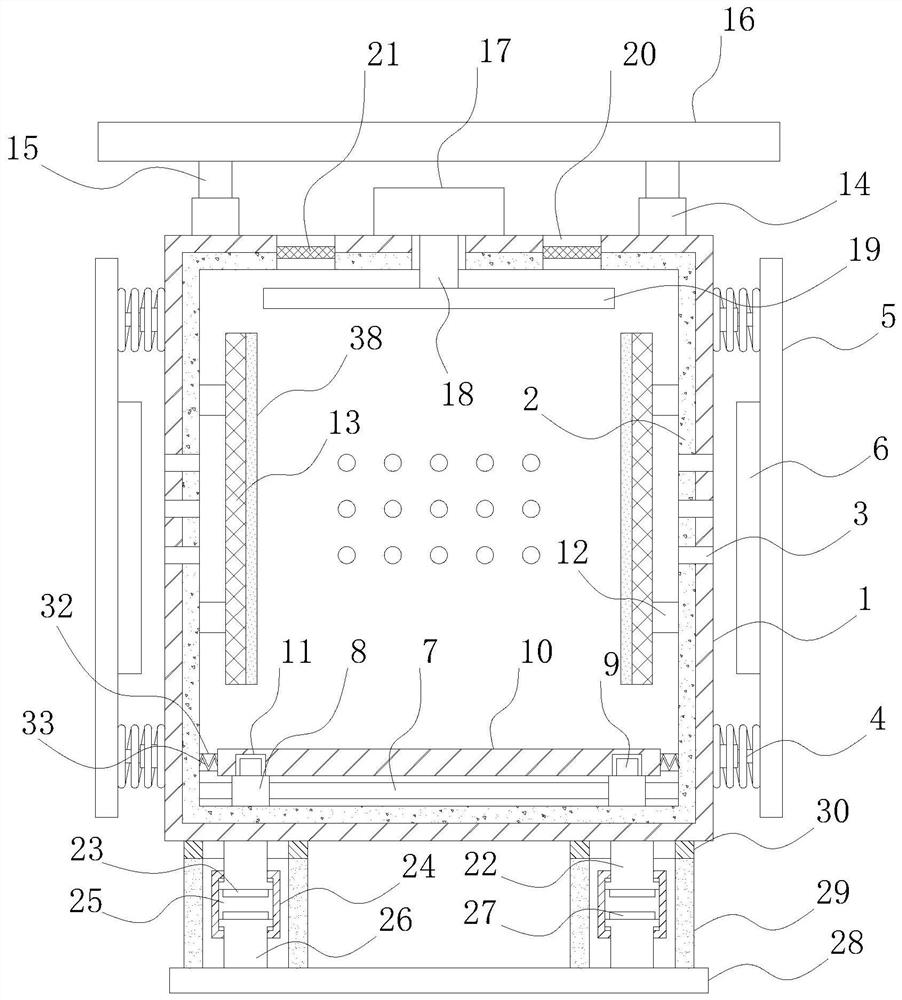
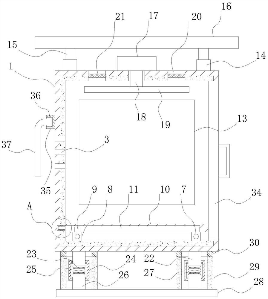
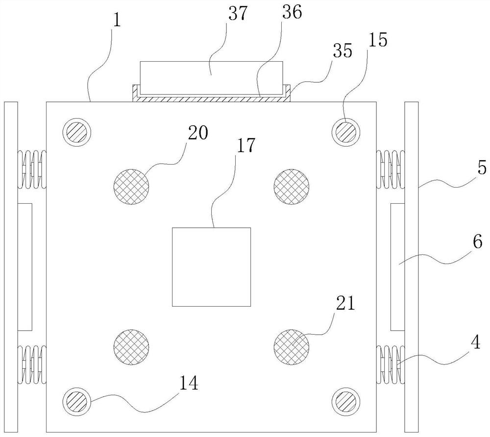
[0023] refer to Figure 1-4 , a distribution box with a buffer function for use on a construction site, including a box body 1, a moisture-proof pad 2 is bonded to the inner surface of the box body 1, through holes 3 are evenly opened around the box body 1, and the box body 1 Both sides of the outer surface are symmetrically welded with buffer springs 4, one end of the buffer spring 4 is welded with an anti-collision plate 5, and the middle part of the anti-collision plate 5 and the buffer spring 4 is welded with a spring pad 6, and the inside of the box body 1 The lower part is symmetrically welded with a fixed rod 7, and the outer surface of the fixed rod 7 is symmetrically welded with a connecting block 8. The top of the connecting block 8 is integrally formed with a clamping block 9, and the clamping block 9 is clamped with a mounting plate 10. The bottom end of the mounting plate 10 There is a first card slot 11 matched with the block 9, and a slider 31 is welded symmetri...

Embodiment 2

[0027] refer to Figure 1-2As another preferred embodiment of the present invention, the difference from Embodiment 1 is that the damping mechanism includes first support columns 22 welded to the four corners of the bottom end of the box body 1, and the bottom ends of the first support columns 22 are welded with first The magnet 23 is slidably connected with a sleeve 24 under the first support column 22, and the middle part of the sleeve 24 is provided with a first chute 25 matched with the first support column 22, and the bottom of the first chute 25 is slidably connected. There is a second support column 26, the top of the second support column 26 is welded with a second magnet 27, the bottom of the second support column 26 is welded with a base plate 28, and the top of the base plate 28 is equipped with an auxiliary shock absorbing mechanism, and the auxiliary shock absorbing mechanism includes Two pairs of hollow elastic columns 29 are welded symmetrically on the top of th...


PUM


Abstract

The invention relates to the technical field of distribution boxes, in particular to a distribution box with a buffer function for construction sites, including a box body, two sides of the outer surface of the box body are symmetrically welded with buffer springs in pairs, and one end of the buffer spring is welded There is an anti-collision plate, the middle part of the anti-collision plate and the buffer spring are welded with a spring pad, the inner bottom of the box is symmetrically welded with a fixed rod, the outer surface of the fixed rod is symmetrically welded with a connecting block, and the top of the connecting block is integrally formed with a clip The mounting plate is clamped on the clamping block, and the bottom end of the mounting plate is provided with the first card slot matching the clamping block. The inner sides of the box are located above the mounting plate and are symmetrically welded with elastic buffer blocks in pairs. One side of the buffer block is welded with a protective net plate. The invention has a buffer function, and can prevent the electrical components inside the distribution box from moving when a collision occurs, so as to avoid affecting the connection between the electrical components and the service life of the electrical components.

Description

technical field [0001] The invention relates to the technical field of distribution boxes, in particular to a distribution box with a buffer function used in a construction site. Background technique [0002] The distribution box is a large number of parameters in the data. It generally constitutes a low-voltage distribution box. box. [0003] The distribution box used in the existing construction site does not have a buffer function, so when a collision occurs, the electrical components inside the distribution box will move, which will affect the connection between the electrical components and the use of the electrical components life. Contents of the invention [0004] The purpose of the present invention is to solve the disadvantage of not having a buffer function in the prior art, and propose a distribution box with a buffer function for use in a construction site. [0005] In order to achieve the above object, the present invention adopts the following technical s...

Claims


Application Information

Patent Timeline
Patent Type & Authority Patents(China)
IPC IPC(8): H02B1/54H02B1/56H02B1/28
CPCH02B1/54H02B1/565H02B1/28
Inventor 徐全启张志强
Owner 枣阳宁远电器设备有限公司
Why Eureka
Try Eureka