
Bimodal bionic vision sensor

A visual sensor, dual-mode technology, applied in picture signal generators, solid-state image signal generators, televisions, etc., can solve the problems of reducing and difficult to take into account at the same time, achieve high image signal-to-noise ratio, improve dynamic range, The effect of increasing the shooting speed

Active Publication Date: 2020-04-28
TSINGHUA UNIV
View PDF4 Cites 17 Cited by
  • Summary
  • Abstract
  • Description
  • Claims
  • Application Information

AI Technical Summary

Problems solved by technology

It can be seen from the above that under the framework of the traditional bionic vision sensor, these three indicators are often mutually exclusive: for example, when the shooting speed increases, the dynamic range of the bionic vision sensor will decrease; when the image quality improves, the shooting speed will generally decrease. reduced, it is difficult to take care of both

Method used

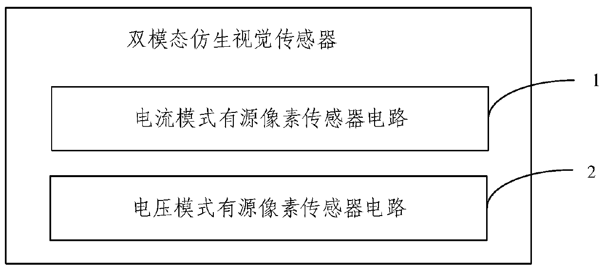
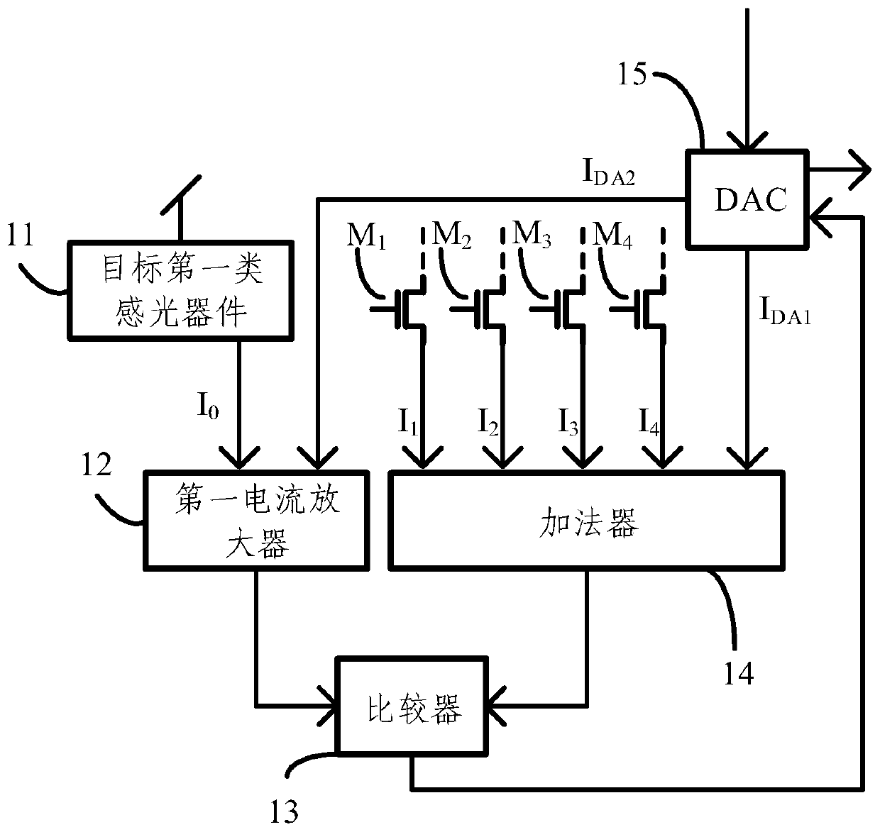
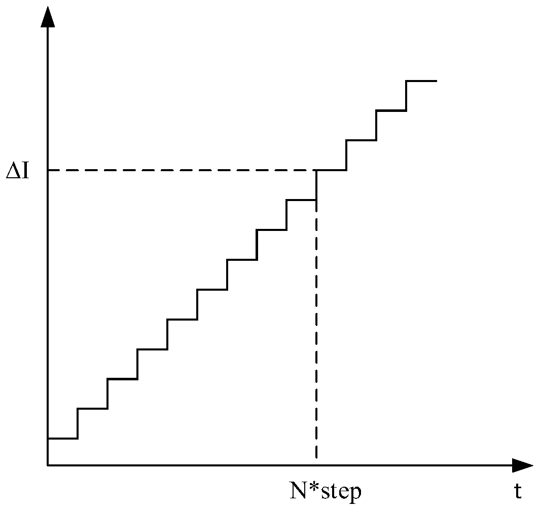

Image

  • Bimodal bionic vision sensor
  • Bimodal bionic vision sensor
  • Bimodal bionic vision sensor

Examples


Embodiment Construction

[0045] In order to make the purpose, technical solutions and advantages of the embodiments of the present invention clearer, the technical solutions in the embodiments of the present invention will be clearly and completely described below in conjunction with the drawings in the embodiments of the present invention. Obviously, the described embodiments It is a part of embodiments of the present invention, but not all embodiments. Based on the embodiments of the present invention, all other embodiments obtained by persons of ordinary skill in the art without creative efforts fall within the protection scope of the present invention.

[0046] In the description of the embodiments of the present invention, it should be noted that the terms "center", "upper", "lower", "left", "right", "vertical", "horizontal", "inner", "outer " and other indicated orientations or positional relationships are based on the orientations or positional relationships shown in the drawings, and are only ...


PUM


Abstract

The embodiment of the invention provides a bimodal bionic vision sensor. The effect of exciting type visual rod cells is simulated through a first type current mode active pixel sensor circuit, and aperception effect on light intensity gradient information in a target light signal is realized, so the dynamic range of a bionic vision sensor image is further improved, and the shooting speed is increased. Moreover, a first type control switch is introduced to each non-target first type photosensitive device, so the obtained light intensity gradient information can be controlled, the adjustment of the dynamic range of the bionic vision sensor image is realized, the adjustment of the shooting speed is further realized, and the effect of reconfiguration is realized. According to the invention,the voltage mode active pixel sensor simulates the effect of the cone cells, a target voltage signal representing the light intensity information in the target light signal can be output, the perception effect on the light intensity information in the target light signal is realized, the obtained target voltage signal represents the light intensity information with higher precision, and the obtained image quality can be ensured.

Description

technical field [0001] The invention relates to the technical field of integrated circuits, and more specifically, to a dual-mode bionic vision sensor. Background technique [0002] With the continuous deepening of research on image sensors and image processing and recognition algorithms, bionic vision sensors play an increasingly important role in many application fields such as industrial manufacturing, intelligent transportation, and intelligent robots. [0003] The bionic vision sensor mainly simulates the mode of the human retina. The human retina mainly includes two kinds of visual perception cells, namely cone cells and rod cells, which correspond to two different modes. Among them, the mode of cone cells is mainly sensitive to absolute light intensity information and color information, and has high image restoration accuracy, but the restoration speed is slow; contrary to the mode of cone cells, rod cells are mainly sensitive to light Perceive the change amount of s...

Claims


Application Information

Patent Timeline
IPC IPC(8): H04N5/369H04N5/3745H04N9/04
CPCH04N25/70H04N25/77H04N23/10H04N25/134H04N25/53H04N25/702H04N25/133G06V10/147H04N25/75
Inventor 施路平杨哲宇赵蓉裴京徐海峥
Owner TSINGHUA UNIV
Learn More