
Printing method and printer capable of realizing small-batch high-speed printing

A high-speed printing, small-batch technology, applied in the direction of copying/marking, printing, object separation, etc., can solve the problems of unfavorable equipment utilization, equipment cost control, screen printing is not suitable for small batch printing, unfavorable equipment cost, etc. , to achieve the effect of low transmission control accuracy, good printing effect, and improved printing accuracy

Active Publication Date: 2020-05-01
驱动数码电子(广东)有限公司
View PDF5 Cites 0 Cited by
  • Summary
  • Abstract
  • Description
  • Claims
  • Application Information

AI Technical Summary

Problems solved by technology

However, since the printing medium passes through the machine at one time, it is required that the printing surface of the spray vehicle must cover the entire transmission platform in the vertical transmission direction, that is, the projected length of the printing surface of the spray vehicle in the vertical transmission direction must be greater than the width of the transmission platform. To print on large-size printing media, more nozzles are needed to meet the printing requirements of large-size printing media, and the nozzles are high-precision accessories, which are expensive, and the more nozzles, the higher the load-bearing requirements of the sprayer. , the difficulty of lifting the spray car is also increasing, which is not conducive to the control of equipment costs. Therefore, the length of the spray car of the current single-pass printer in the vertical conveying direction is limited, and the format of the printing medium it can print is also limited.
[0006] For some large-sized printing media, although the target pattern to be printed does not cover the entire printing medium, the relative position between the target pattern and the printing medium is not fixed, resulting in the length of the printing vehicle in the vertical conveying direction not being less than the length of the printing medium. The length in the vertical transmission direction, the sprayer not only has no way to reduce its length in the vertical transmission direction with the target pattern, but also far exceeds the maximum projection distance of the target pattern in the vertical transmission direction, which is not conducive to equipment utilization. Improvement and control of equipment costs
At present, screen printing is generally used for the printing of such large media and small patterns, but screen printing is not suitable for small batch printing, and the production of screens requires a certain amount of time and cost, so it is necessary to improve the existing printing technology Improve

Method used


Image

  • Printing method and printer capable of realizing small-batch high-speed printing
  • Printing method and printer capable of realizing small-batch high-speed printing
  • Printing method and printer capable of realizing small-batch high-speed printing

Examples


Embodiment 1

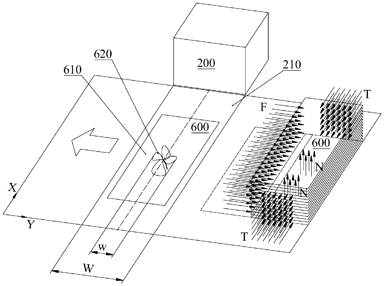
[0033] Such as figure 1 As shown, a small-batch high-speed printing printing method is used to print a target pattern 620 on a target area 610 of a discontinuous medium, including the following steps:

[0034] S1. Convey the medium along the Y direction to the position where the print format of the spray vehicle covers the target area 610 or the target area 610 covers the print format of the spray vehicle, and stop the transmission after reaching the position;

[0035] S2. The spray vehicle moves along the X direction, and prints the target pattern 620 on the target area 610 of the medium during the moving process;

[0036] Wherein, the Y direction and the X direction are perpendicular to each other, and the projected length w of the target pattern 620 in the Y direction is smaller than the projected length W of the inkjet print surface in the Y direction.

[0037] The present invention is different from the traditional multi-pass and single-pass printing modes, and creativel...

Embodiment 2

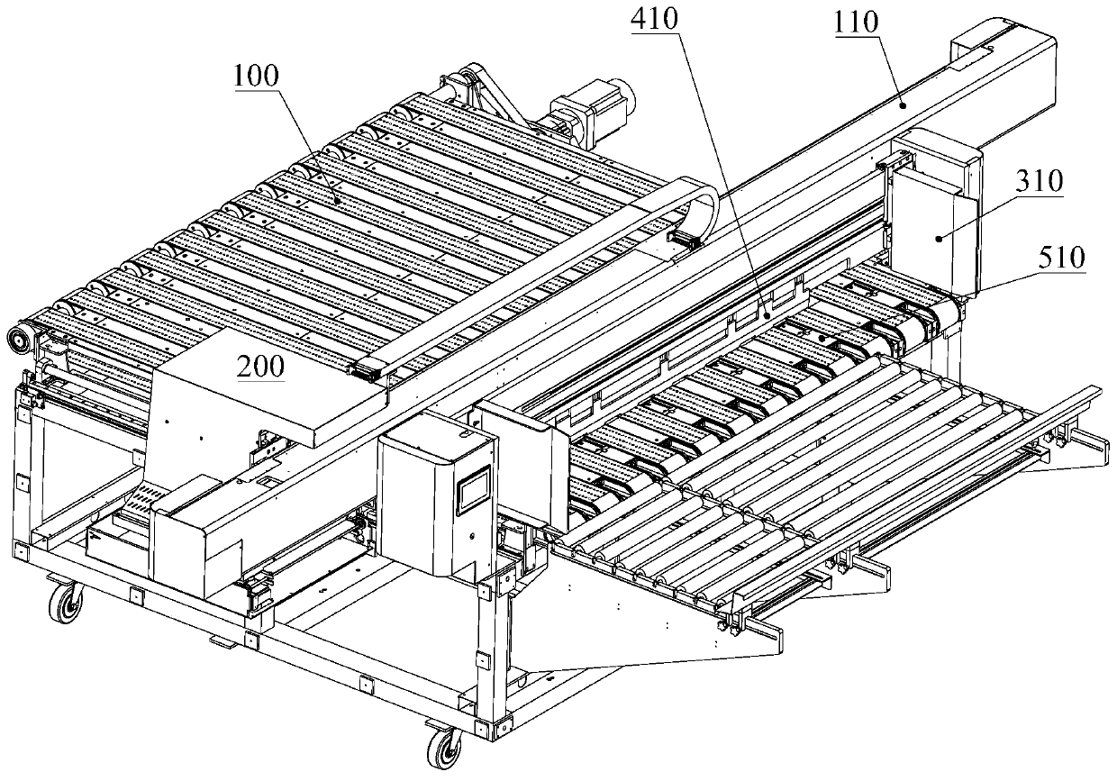
[0043] Such as figure 2 As shown, a small batch high-speed printing printer for printing target patterns on target areas of non-continuous media, including

[0044] The conveying platform 100 is used to convey the medium from the back to the front, and has a conveying direction Y; and

[0045] The spray vehicle is movably arranged above the conveying platform 100 and has a displacement direction X perpendicular to the conveying direction Y. The projected length W of the print format of the sprayed vehicle in the conveying direction Y is greater than the projected length of the target pattern in the conveying direction Y w;

[0046] Before printing, the conveying platform 100 conveys the medium to the position where the printing surface of the jetting vehicle covers the target area or the target area covers the printing width of the jetting vehicle, and the target pattern is printed after the medium is transported in place.

[0047] The present invention is different from th...


PUM


Abstract

The invention relates to the technical field of industrial printing, and discloses a printing method capable of realizing small-batch high-speed printing. The printing method is used for printing a target pattern in a target area of a discontinuous medium and includes the following steps that S1, the medium is transferred in the Y-direction to the position where the target area is covered by the spraying car printing width or the spraying car printing width is covered by the target area, and transferring is stopped after the medium is in place; S2, a spraying car moves in the X-direction and prints the target pattern in the target area of the medium during movement; the Y-direction is perpendicular to the X-direction, and the projection length w of the target pattern in the Y-direction issmaller than the projection length W of the spraying car printing width in the Y-direction. The method is different from traditional multi-PASS and single-PASS printing modes and creatively puts forward the 1-PASS printing mode applicable to small-batch high-speed and high-quality printing. The printing quality and the printing speed are guaranteed, the requirement for the transferring control precision is low, the size of the spraying car in the X displacement direction can be reduced to the maximum extent, and the cost and the vacancy rate of resources can be reduced.

Description

technical field [0001] The invention relates to the technical field of industrial printing, and more specifically, to a printing method and a printer for small-batch high-speed printing. Background technique [0002] Industrial printers are widely used in the printing of large-sized printing media such as tiles, wood boards, glass, corrugated paper, and buckle boards. They print inks of various colors or effects on the printing media through inkjet methods and then further process them to obtain the expected results. Pattern, during the printing process, the ink penetrates into the interior of the printing medium through corrosion, so that the pattern obtained by inkjet printing is not easy to fade, and has the characteristics of waterproof, anti-ultraviolet, and anti-scratch. [0003] In the prior art, industrialized printers generally include a transfer platform for transferring printing media and a spray truck equipped with nozzles for printing above the transfer platform...

Claims


Application Information

Patent Timeline
Patent Type & Authority Applications(China)
IPC IPC(8): B41M5/00B41J2/01B65H3/08
CPCB41M5/00B41J2/01B65H3/085B65H2701/1131B41J3/407
Inventor 万弋林汤振宇
Owner 驱动数码电子(广东)有限公司
Learn More