
Vehicle body and rail transit vehicle

A car body and air duct technology, which is applied in the field of rail transit vehicles, can solve the problems of small visual range of passengers and poor riding experience, and achieve the effects of improving riding experience, reducing psychological burden, and increasing the see-through area

Active Publication Date: 2020-05-01
ZHUZHOU ELECTRIC LOCOMOTIVE CO
View PDF7 Cites 1 Cited by
  • Summary
  • Abstract
  • Description
  • Claims
  • Application Information

AI Technical Summary

Problems solved by technology

[0002] At present, most of the car bodies of rail vehicles are made of aluminum alloy frames, aluminum honeycomb panels and composite materials, and only the window mounting holes are opened on the side walls, so that the passenger's viewing range is small and the riding experience is poor.

Method used


Image

  • Vehicle body and rail transit vehicle
  • Vehicle body and rail transit vehicle
  • Vehicle body and rail transit vehicle

Examples


Embodiment 1

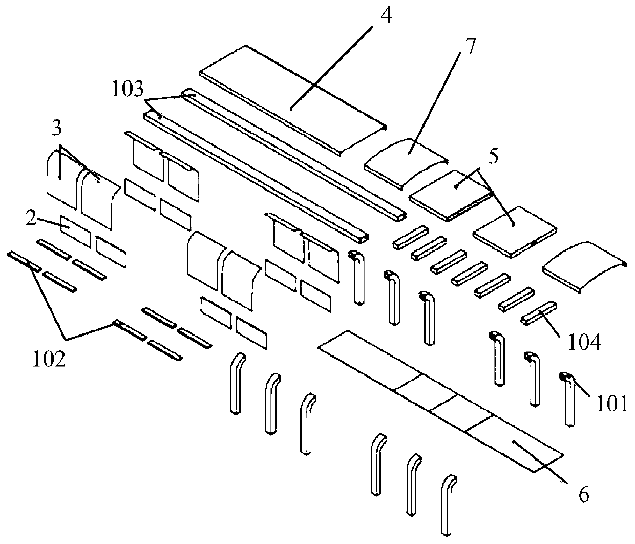
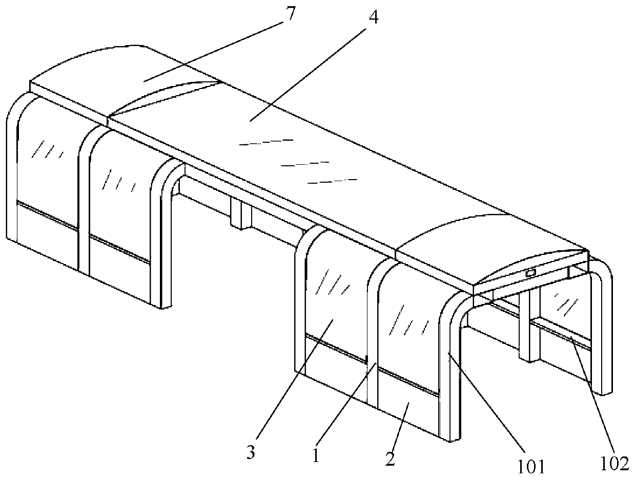
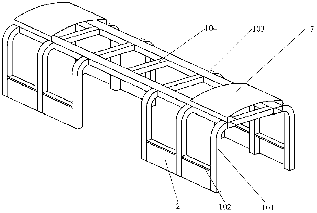
[0050] The invention discloses a vehicle body, wherein the vehicle body comprises a vehicle body frame 1 , a side wall panel 2 , a side wall glass 3 and a top cover glass 4 .

[0051] The side wall panels 2 and the side wall glass 3 are all sealed and installed on the side of the car body frame 1, and the height of the side wall panels 2 is a preset height. Here, it should be noted that the preset height refers to a height that avoids fear of passengers, and can Set as needed.

[0052] The side wall glass 3 is located above the side wall panel 2, and the top of the side wall glass 3 extends to the roof side beam side wall of the car body frame 1 in an arc shape, which helps to expand the viewing angle.

[0053] The top cover glass 4 is hermetically installed on the top of the car body frame 1 to increase the perspective area.

[0054] In the vehicle body disclosed by the present invention, since the side wall glass 3 is located above the side wall panel 2, the psychological b...

Embodiment 2

[0057] In the second embodiment provided by the present invention, the structure of the vehicle body in this embodiment is similar to the structure of the vehicle body in the first embodiment, so the similarities will not be repeated, and only the differences will be introduced.

[0058] In this embodiment, the present invention discloses that the car body further includes an air-conditioning ventilation duct 5, which is slidably mounted on the top of the car body frame 1 and is located below the roof glass 4; when the air-conditioning ventilation duct 5 When the track slides and closes, the top of the car body can be closed, so that the bottom of the car body forms a closed cavity to the air-conditioning ventilation duct; when the air-conditioning ventilation duct 5 slides open, the top cover glass can be exposed. That is, the air-conditioning ventilation duct 5 can be slid open to expose the roof glass 4 or slid closed to cover the roof glass 4 . Under the action of the addi...

Embodiment 3

[0077] The present invention provides a rail transit vehicle, including the vehicle body in any one of the above embodiments.


PUM


Abstract

The invention discloses a vehicle body and a rail transit vehicle. The vehicle body comprises a vehicle body framework, side wall plates, side wall glass and top cover glass. The side wall plate and the side wall glass are installed on the side face of the vehicle body framework, the height of the side wall plate is a preset height, the side wall glass is located above the side wall plate, and thetop of the side wall glass extends to the side wall of a top cover edge beam of the vehicle body framework in an arc shape. Top cover glass is installed at the top end of the vehicle body framework.As the side wall glass is positioned above the side wall plate, the psychological burden of passengers is reduced. The top of the side wall glass extends to the side wall of the top cover edge beam ofthe vehicle body framework in an arc shape, and the perspective angle of the side glass is increased. Top cover glass is installed at the top end of the vehicle body framework, and the perspective area is increased. In conclusion, the vehicle body provided by the invention can enlarge the visual range of passengers and improve the riding experience of the passengers.

Description

technical field [0001] The invention relates to the technical field of rail transit vehicles, in particular to a vehicle body and a rail transit vehicle. Background technique [0002] At present, most of the rail vehicle body is made of aluminum alloy frame, aluminum honeycomb panel and composite materials, and only the window mounting holes are opened on the side wall, so that the passenger's viewing range is small and the riding experience is poor. [0003] Therefore, how to increase the visual range of passengers and improve the ride experience of passengers is a technical problem to be solved urgently by those skilled in the art. Contents of the invention [0004] In view of this, the first object of the present invention is to provide a vehicle body that can increase the visual range of passengers and improve the riding experience of passengers. [0005] The second object of the present invention is to provide a rail vehicle. [0006] In order to realize above-menti...

Claims


Application Information

Patent Timeline
Patent Type & Authority Applications(China)
IPC IPC(8): B61D17/08B61D17/12B61D17/00B61D25/00
CPCB61D17/00B61D17/08B61D17/12B61D25/00
Inventor 严银金希红苏永章曾燕军王锴闵阳春
Owner ZHUZHOU ELECTRIC LOCOMOTIVE CO
Learn More