Storage device of mold steel

A technology for storage devices and steel materials, applied in storage devices, devices for coating liquid on the surface, transportation and packaging, etc., can solve the problems of high labor intensity, hidden dangers of steel products, etc., and achieve the effect of convenient fixed connection

Active Publication Date: 2020-05-01
重庆禾秀丰电子有限公司
View PDF8 Cites 2 Cited by
  • Summary
  • Abstract
  • Description
  • Claims
  • Application Information

AI Technical Summary

Problems solved by technology

[0005] The present invention intends to provide a storage device for mold steel to solve the problems in the prior art that the steel is manually transported to the storage rack and the labor intensity of the manual arrangement of the steel is high, and there are safety hazards in the manual handling and manual movement of the steel question

Method used


Image

  • Storage device of mold steel
  • Storage device of mold steel
  • Storage device of mold steel

Examples


Embodiment 1

[0037] Embodiment 1 is basically as attached Figure 1 to Figure 5 shown:

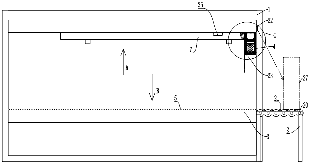
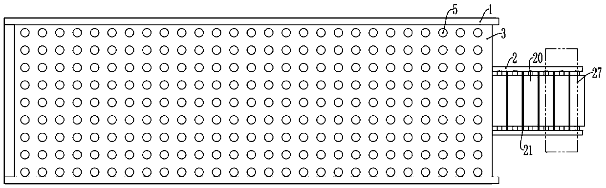
[0038] A storage device for mold steel, including a storage rack 1 and a support rack 2 fixed on the ground by screws, the support rack 2 is located on the right side of the storage rack 1, and a placement platform 3 and a push unit 4 are installed on the storage rack 1, and the storage rack 1 is provided with a placing platform 3 and a pushing unit 4. The platform 3 is fixed and installed on the storage rack 1 by bolts, and the material of the placing platform 3 is 27 steel; there are several balls 5 connected to the placing platform 3 in rotation, that is, the placing platform 3 is a platform with the balls 5, which is convenient for subsequent heavy lifting. Movement of the steel 27 on the placement platform 3 .

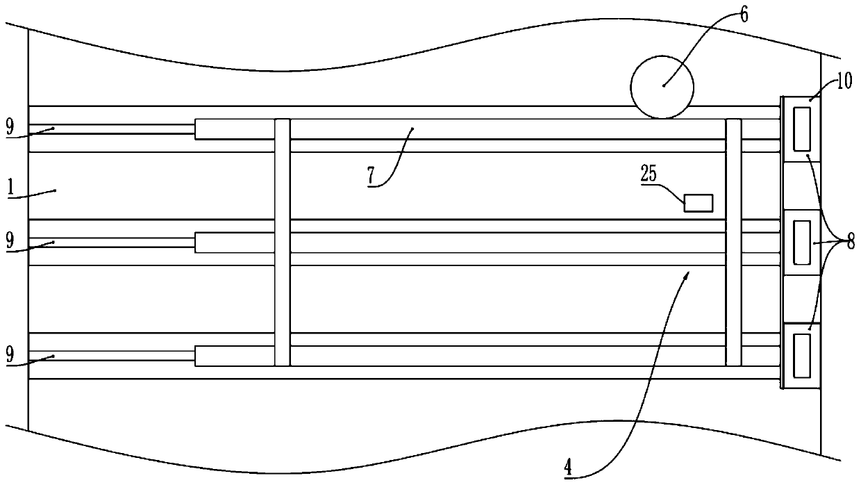
[0039] combine figure 2 and Figure 4 , the push unit 4 includes a motor, a gear 6, a moving frame 7 and a grabbing assembly 8, the motor is fixedly installed on the storage frame, the...

Embodiment 2

[0055] The second embodiment is basically as attached Image 6 As shown, the second implementation is improved on the basis of the first embodiment, and the details are as follows:

[0056] Three layers of placing platforms 3 are installed on the storage rack 1 , and a pushing unit 4 is installed above each placing platform 3 (the pushing unit 4 is installed at the bottom of the previous placing plane), and the bottom of the supporting frame 2 is fixedly connected with a lifting platform 26 .

[0057] The lifting platform 26 drives the support frame 2 to move, so that the rollers 20 can be level with the balls 5 on the corresponding placing platform 3 , so that the steel materials 27 can be stored on the placing platforms 3 of different heights, so that more steel materials 27 can be stored.


PUM


Abstract

The invention relates to the technical field of storage devices, and specifically discloses a storage device of mold steel. The storage device comprises a storage frame and further comprises a supporting frame located on one side of the storage frame. Multiple rollers are connected to the supporting frame in a rotating manner. The multiple rollers are horizontally arranged. The adjacent rollers are parallel to one another. A containing platform and a pushing unit are arranged on the storage frame. Multiple balls are connected to the containing platform in a rotating manner. The upper surfacesof the rollers and the top ends of the balls are on the same plane. The pushing unit comprises movable frames and grabbing assemblies. The movable frames are connected to the storage frame in a sliding manner. The grabbing assemblies are fixedly connected to the end portions of the movable frames. The grabbing assemblies are located above the rollers. The pushing unit is used for pushing the steelon the rollers onto the containing platform. The storage device is used for solving the problems that in the prior art, due to the fact that the steel is manually carried onto the storage frame and is manually arranged, the labor intensity is high and the problem that potential safety hazards exist in manual steel carrying and movement.

Description

technical field [0001] The invention relates to the technical field of storage devices, in particular to a storage device for mold steel. Background technique [0002] The mold factory that produces injection parts has a large number of injection molds. Because injection parts require high clamping force during molding, the material requirements for injection molds are relatively high. In this industry, steel is generally used as the only material for injection molds. [0003] When making injection molds, different mold parts should be made according to the structure of different injection parts, such as concave template, convex template, slider, etc. Most of these structures of each injection part are unique, and the structure of these parts needs to be adopted. Different equipments process the steel multiple times. Before the steel for making the parts has not been processed for all the work, it is necessary to place the steel that has not yet been processed on the storage...

Claims


Application Information

Patent Timeline
Patent Type & Authority Applications(China)
IPC IPC(8): B65G1/04B05C1/06
CPCB05C1/06B65G1/04
Inventor 陈奕超贺申虎
Owner 重庆禾秀丰电子有限公司
Why Eureka
Try Eureka